the Creative Commons Attribution 4.0 License.
the Creative Commons Attribution 4.0 License.
ICON-ART 2.1: a flexible tracer framework and its application for composition studies in numerical weather forecasting and climate simulations
Jennifer Schröter
Daniel Rieger
Christian Stassen
Heike Vogel
Michael Weimer
Sven Werchner
Jochen Förstner
Florian Prill
Daniel Reinert
Günther Zängl
Marco Giorgetta
Roland Ruhnke
Bernhard Vogel
Peter Braesicke
Atmospheric composition studies on weather and climate timescales require flexible, scalable models. The ICOsahedral Nonhydrostatic model with Aerosols and Reactive Trace gases (ICON-ART) provides such an environment. Here, we introduce the most up-to-date version of the flexible tracer framework for ICON-ART and explain its application in one numerical weather forecast and one climate related case study. We demonstrate the implementation of idealised tracers and chemistry tendencies of different complexity using the ART infrastructure. Using different ICON physics configurations for weather and climate with ART, we perform integrations on different timescales, illustrating the model's performance. First, we present a hindcast experiment for the 2002 ozone hole split with two different ozone chemistry schemes using the numerical weather prediction physics configuration. We compare the hindcast with observations and discuss the confinement of the vortex split using an idealised tracer diagnostic. Secondly, we study AMIP-type integrations using a simplified chemistry scheme in conjunction with the climate physics configuration. We use two different simulations: the interactive simulation, where modelled ozone is coupled back to the radiation scheme, and the non-interactive simulation that uses a default background climatology of ozone. Additionally, we introduce changes of water vapour by methane oxidation for the interactive simulation. We discuss the impact of stratospheric ozone and water vapour variations in the interactive and non-interactive integrations on the water vapour tape recorder, as a measure of tropical upwelling changes. Additionally we explain the seasonal evolution and latitudinal distribution of the age of air. The age of air is a measure of the strength of the meridional overturning circulation with young air in the tropical upwelling region and older air in polar winter downwelling regions. We conclude that our flexible tracer framework allows for tailor-made configurations of ICON-ART in weather and climate applications that are easy to configure and run well.
- Article
(33947 KB) - Full-text XML
- BibTeX
- EndNote
Until recently, most global numerical weather prediction (NWP) and climate models were built upon the approximate hydrostatic primitive set of equations, which hindered their application on convective scales (O(1 km)) or below. With the advent of next-generation global modelling systems like MPAS (Skamarock et al., 2012), NICAM (Tomita and Satoh, 2004), UM-UKCA (Hewitt et al., 2011) or ICON (Zängl et al., 2015), this restriction has been overcome, as they rely on a fully compressible set of hydro-thermodynamical equations (i.e. the acceleration term dw∕dt in the vertical momentum equation is no longer neglected). In principle, this allows the same dynamical core to be applied across the entire range of temporal and spatial scales that exist in the atmosphere. Thus, simulations ranging from a few hours to hundreds of years may become more consistent and advances of one scale or application can more easily be transferred to another. However, the construction of scale-aware physical parameterisations that can be applied over the entire range of scales remains a challenge (Chun et al., 2016; Rauscher et al., 2013).
The extended modelling system ICON-ART (Rieger et al., 2015) is a representative of a next-generation system. ICON (Zängl et al., 2015) is a joint development of Deutscher Wetterdienst (DWD) and Max Planck Institute for Meteorology (MPI-M). The dynamical core of ICON is based on the nonhydrostatic formulation of the vertical momentum equation. Thus, ICON allows simulations with high horizontal resolutions, up to grid spacings of a few hundreds of metres. However, while the dynamical core of ICON is unified, individual applications like large eddy simulations (LESs), NWP or climate projections, e.g. EC(MWF) HAM(burg) (ECHAM), currently use different parameterisations of physical processes (Dipankar et al., 2015; Heinze et al., 2017).
ICON offers the possibility of local grid refinements, also called “nesting”. The nesting provides the option of two-way interactions between the (global) coarse domain and the higher-resolution local domain. Hierarchical nesting and several domains at the same nesting level are possible. ICON already provides benefits in various application fields, e.g. in the High Definition Clouds and Precipitation for advancing Climate Prediction (HD(CP)2) project. Selected results of the HD(CP)2 project are described in Heinze et al. (2017). Within this project, the configuration of the LES physical configuration has been developed and is used to achieve a better understanding of, for example, processes that are related to precipitation. Results will help to improve future climate projections on coarser resolutions.
Since January 2015, ICON has been running operationally at DWD for weather forecasts on the global scale with a grid spacing of 13 km. Since June 2015, a local grid refinement over Europe with a horizontal resolution of 6.5 km has been in operational use as well.
ART is an additional module for ICON, developed at the Karlsruhe Institute of Technology. It contributes to the goal of a unified global next-generation modelling system with a variety of applications in the field of atmospheric composition sciences. A variant of the ART module is also being used in COSMO-ART. However, parameterisations differ and implementations have been updated to newer Fortran standards. ICON-ART extends the numerical weather and climate prediction system ICON with (gas-phase) chemistry, aerosol dynamics and related feedback processes. A comprehensive treatment of feedback processes between chemistry, aerosols, clouds and radiation can now be included in recent and future studies (Eckstein et al., 2017; Gasch et al., 2017; Rieger et al., 2017; Weimer et al., 2017).
Here, we will discuss the unified tracer framework of ICON-ART that allows to define and specify tracer initialisation and a coupling of individual chemical mechanisms and specific process modules. Depending on the requirements of the application field, like large eddy simulations, numerical weather predictions or climate simulations, ICON-ART can run with the different existing physics configurations.
Given the multitude of challenges we are facing, models have to be capable of being readily changed. Therefore, it is of high importance to provide a tracer framework that is flexible and suitable for a large variety of different applications. For the development of next-generation modelling systems, the requirements for modern high-performance computer architectures also have to be considered. Nowadays, numerical models are integrated on massively parallel architectures with up to 106 cores. Unstructured grids like the icosahedral ICON grid show advantages regarding the performance on current high-performance computing systems (Zängl et al., 2015). Taking into account the increase of computational power over the last years, it is obvious that more diagnostic and prognostic tracers will be included in future simulations than before. With ICON-ART 2.1, we introduce a new flexible tracer framework, which meets the demands of a next-generation modelling system. There is full flexibility in defining the tracers and associated characteristics. The set of tracers can be tailored for individual experimental setups of different complexity. The model allows for changes in the set of tracers without any recompilation. The ability to replace the common usage of namelist structures, previously used by ICON-ART and other models (Baklanov et al., 2014; Morgenstern et al., 2017), is fully supported.
Here, we describe the concept of the new ICON-ART tracer framework. The technical description is followed by examples of definitions for chemical and passive tracers in ICON-ART in Sect. 5. In Sect. 5, we give an overview of different applications of ICON-ART using the flexible tracer framework. These applications include simulations with the numerical weather prediction physics configuration and simulations with the climate physics configuration. We finish with some concluding remarks and an outlook.
For the simulation of the chemical composition of the Earth's atmosphere, it is highly desirable to be able to design individual experiments on different temporal and spatial scales. For example, if an experiment is focusing on tropospheric chemical composition, it is useful to define many emission-driven tropospheric chemical tracers. For long-term simulations, it might be advantageous to define a smaller subset of chemical tracers leading to a less expensive calculation in terms of computational time. In addition, sometimes chemical tracers with a short lifetime, compared to dynamical timescales, can be neglected in the transport processes.
With ICON-ART, we introduce a flexible tracer framework with a minimum of predefinitions that allows all of the above and more. The user has the ability to define a unique set of tracers, tailored to the requirements of the model experiment planned. The new tracer framework builds on structures which are already implemented in the basic ICON framework and shared by different available physical configurations. These configurations are the LES physics configuration (Dipankar et al., 2015; Heinze et al., 2017), the NWP physics configuration and the climate physics configuration based on ECHAM6 parameterisation (Giorgetta et al., 2018). The new tracer framework allows flexible coupling to the selected physical configuration. Thus, the composition coupling can be performed without subsequent changes. The ART code is not changed when the physics configuration is changed.
This allows an independent investigation of atmospheric processes using different physical configurations.
2.1 Technical description of the tracer framework
The technical framework of ICON-ART is based on Fortran 2008, which
provides essential functionality for the new tracer framework. Classes allow
to overcome the stringent matching of data types. Items only have to match a
data type or any extension of this type when it is declared with
CLASS(type) where type is a derived data type
(Chapman, 2008). If the CLASS matches more than one data
type, it is called polymorphic. Within ICON-ART, we are using these
polymorphic objects to extend the existing tracer structure by additional
metadata. Linked lists are another Fortran 2008 feature that is
extensively used. Linked lists allow for new features like passing a
reference to the next list element or adding and deleting elements.
In the scope of this paper, we are working with two different types of tracers: passive and chemical active ones. An example for a passive tracer is a constituent that does not have any impact on other tracers or the thermodynamics of the simulated system. Passive tracers have predefined sources or only fixed initial conditions. They change by transport and do not interact with other tracers or processes. Chemical active tracers experience sources and sinks while being transported and can participate in feedback processes.
Passive and chemical active tracers are distinguished by their associated metadata. In our example, passive tracers have no chemical loss term to be considered. In other words, the lifetime of passive tracers is infinite. Information about the lifetime is used for simple chemical tracers that experience an idealised loss while being transported. Of course, the information dealing with transport should be provided for both tracer types. A flexible aerosol dynamics module making use of the flexible tracer framework is currently undergoing development.
2.2 Storage of metadata information
We extend the existing ICON-ART functionality by the usage of a key-value storage. The storage is based on string comparisons using generic hash tables. For every tracer, a unique key of fixed size is defined. This represents the search key. The table is constructed like a dictionary. Tracer information can be looked up fast, using this search key. Hash tables provide the foundation for a generic and flexible concept to read and store metadata. At model initialisation, one key-value storage for each tracer is initialised by
CALL storage%init(lcase_sensitivity=.FALSE.)
In this case, the dictionary entries are not case sensitive. The storage unit
has two fundamental subroutines; these are storage%put and
storage%get. The first creates a new dictionary entry, and the
second searches for a key and gives the connected entry. In the next step,
this storage unit has to be filled. Accepted types of storage values are
reals, integers or characters.
2.2.1 Reading in metadata information from XML files
At one point in time, all numerical models need to find an answer to the question how to transfer text-based information (e.g. tracer metadata) into the model's program code. The text-based format XML (eXtensible Markup Language) (W3C-Recommendation, 2017) gives the developer and the user the ability to store and transport information in a structured way.
XML has only few mandatory rules; e.g. there has to be exactly one root element. The framework in which the information is structured can be freely chosen. The structure itself allows for a human readable format. ICON-ART uses the Fortran interface TiXI (https://github.com/DLR-SC/tixi, last access: 27 September 2018) to read the XML file. The TiXI interface includes a flexible mechanism for XML file reading. Since the scripting language of XPath is used, the navigation through an XML document is an easy task to perform. The XML reading routine can be structured in the same way as someone would read a document and remember the content in the most natural way. An example structure of such an XML input file for the tracer structure is the following:
<?xml version="1.0" encoding="UTF-8"?>
<!DOCTYPE tracers SYSTEM "tracers_gp.dtd">

<tracers>
 <chemical id="TRO3">
  <mol_weight type="real"> 4.800E-2 </mol_weight>
  <lifetime type="real"> 2592000 </lifetime>
  <transport type="char"> stdchem </transport>
  <init_mode type="int"> 0 </init_mode>
  <unit type="char"> mol mol-1 </unit>
  <long_name type="char"> ozone </long_name>
 </chemical>
</tracers>
The XML file is scanned automatically. For the realisation of this feature,
it is necessary to predefine the type of input. Every tag has a mandatory
type definition, i.e. char, int and real. The first word
in brackets, <tracers>, is called XML tag. The tag <chemical id=''TRO3''> has the additional attribute id for the tag
chemical. To identify a specific tracer, the system uses the given
attribute (e.g. id). Tags are used to build up the metadata
structure. It is a key-value storage where the tag (e.g.
mol_weight) is the key with the value, e.g. 4.800E-2 for
ozone. The number 4.800E-2 is then stored in the metadata structure
of ICON-ART. At this point, it should be noted that there are two kinds of
metadata: necessary and optional metadata. Necessary metadata depend on the
polymorphic type. Passive tracers do have different necessary metadata than
chemical tracers. The optional metadata are read in automatically. Every tag
in the XML file is translated into an entry in the key-value storage.
The structure of the ART tracer framework is shared with the core ICON tracer framework and only expanded in the cases needed. In addition to that, tracers can share attributes and are distinguished by additional attributes. In our example, ozone appears in two different subroutines for chemistry: the first using a lifetime-based mechanism, and the second using a full gas-phase approach.
The tag <mol_weight> can be used for unit conversion within a
subroutine and is given in kg mol−1. The tag <lifetime>
is used for simplified integration methods for a given lifetime of a
species, in seconds. Some chemical substances or passive tracers do not have
to be transported; thus, the tag <transport> ensures that this
information is transferred to the program code and the transport is switched
on or off, respectively. In addition to that, templates can be defined. In
this case, a template named stdchem is chosen. At model startup,
this template is translated into a specific selection of horizontal and
vertical transport schemes. Each scheme stands for a specific numerical
discretisation of the mass continuity equation in horizontal or vertical
directions. Currently, there are three different default transport templates
available: off, stdaero and stdchem. These
templates avoid the necessity of adding a tracer advection scheme and flux
limiter for each single tracer in the namelist. Hence, the values of the
ICON-ART namelist parameters ihadv_tracer, ivadv_tracer,
itype_hlimit and itype_vlimit are overwritten by the
template. Specific information concerning the advection schemes mentioned can
be found in the official ICON documentation. Specifying off will
deactivate advective transport for this tracer completely.
The transport template stdchem uses the same advection schemes as
stdaero. However, the considerably faster positive definite flux
limiters are used instead of the monotone flux limiter. The conservation of
linear correlations is traded for a faster computation of the advection.
If chemical species need to be initialised, this is achieved via
<init_mode> and a respective number corresponding to the
initialisation scheme. If the init_mode is set to 0, no external
initialisation data are used. With integers different from zero, data from
other models, like EMAC (Jöckel et al., 2005) or MOZART
(Emmons et al., 2010), interpolated on the horizontal icosahedral grid are
read in and used. The vertical interpolation is performed online. Thus, the
initialisation dataset stays unchanged, regardless of the choice of model
levels for the simulation.
The structure of the key-value storage for every tracer is built up automatically. This feature allows for an extensive flexibility which has to be controlled. In our case, attributes are used in a fixed manner; they define our basic framework of the tracer structure. The full flexibility, direct access, control mechanisms and data type distinction are only a few advantages of this XML-based procedure against other currently used strategies.
2.3 Construction of the tracer metadata structure
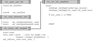
Within ICON-ART, the metadata, e.g. regarding transport or chemical properties, are read in using the XML interface. Afterwards, the information is stored in the ICON-ART tracer framework. The individual steps of the tracer transport simulation in ICON and ICON-ART are described in Rieger et al. (2015). Figure 1 shows the calling structure of the tracer framework in ICON-ART with regard to the tracer and metadata construction. All tracers within the ICON-ART tracer framework share a common structure like the following:
TYPE t_tracer_meta
...
END TYPE t_tracer_meta
In the case of chemical tracers, we want to provide additional information on, e.g. mol weight. The extension of the derived type looks like this:
 TYPE, EXTENDS(t_tracer_meta) :: t_chem_meta
  REAL(wp)    mol_weight
 END TYPE t_chem_meta
In this case, the mol_weight is mandatory information. Optional
metadata are stored in as part of the basic structure
t_tracer_meta. This container includes a key-value storage. This
solution ensures that the metadata container stays as flexible as possible.
The respective XML file is read in, and all information is processed and
stored in the opt_meta container; see Fig. 1. In
the example of mol_weight, this attribute becomes a real variable
accessible in the code. It can be accessed by using, e.g.
SELECT TYPE(meta => info_dyn%tracer)
 CLASS IS (t_chem_meta)
  CALL meta%opt_meta%get('mol_weight', &
       & mol_weight, ierror)
END SELECT
Here, CALL meta%opt_meta%get(…) is the operation to access
the key-value storage in the container.
The combination of linked lists, polymorphic classes and key-value storage allows the user to define tracers in a flexible way. Only those tracers given in an input file are read in, registered and appear in the modelling system. With this solution, the user is free to define any number of chemical or passive tracers which is only limited by the memory of the computing system.
2.4 Construction of XML tracer input file via MECCA
The XML file can either be edited manually by the user or generated automatically by an external program. The tracer files used for the experiments described in Sect. 5 are shown in Appendix A. In this section, we demonstrate the XML file generation by an external program, which also extends the functionality of ICON-ART. In addition to the existing lifetime-based chemistry approach (Rieger et al., 2015), a full gas-phase chemistry approach is added.
Construction of the full gas-phase chemistry approach is done using the comprehensive and flexible atmospheric chemistry module MECCA (Sander et al., 2011). MECCA provides a set of chemical reactions covering the troposphere as well as the stratosphere. The base version of MECCA is extendable by its own chemical reactions or an update of rate coefficients.
The MECCA preprocessing part has been extended by a routine constructing the XML file for the tracer module of ICON-ART. The numerical flexibility of MECCA is based on the KPP software (Sandu and Sander, 2006). KPP generates Fortran90 code which is used to solve the differential equations based on the given chemical reaction. This is the first step which is needed for KPP and thus for MECCA. In a second step, the numerical integrator is chosen. For our example, we use the Rosenbrock solver of the third order (Sandu et al., 1997). In the third step, we use the driver part of MECCA. The driver stands for the main program which calls the integrator, reads input datasets and writes the results in the original MECCA model. Within ICON-ART, we replaced this step by routines of ICON and ICON-ART. Only the integrator call element is maintained. A shell script, in combination with the AWK scripting language (Aho et al., 1987) processes all information and generates the respective files and routines. Technical work has been done to ensure that a dictionary is accessible for the translation between four-dimensional chemical tracers in ICON-ART and one-dimensional concentrations of chemical species in the KPP routines.
Additionally, other chemical reaction mechanisms provided by MECCA can be used within ICON-ART without changes in the program code itself. It is sufficient to read the new tracer XML file generated by the MECCA preprocessor. Finally, all standard reaction schemes provided by MECCA are accessible in ICON-ART by only using MECCA as an external preprocessor. The model has to be recompiled once, but the user does not have to perform changes in the program code. Files that are changed by the preprocessor are copied to the respective ICON directory automatically. Photolysis rates are calculated using an updated version of CloudJ7.3 (Prather, 2015).
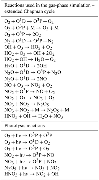
In the scope of this paper, we use a chemical reaction mechanism based on the extended Chapman cycle to demonstrate the functionality of the ICON-ART gas-phase routine.
We defined the chemical reactions as shown in Table 1.
The general coupling structure using NWP physics configuration is described in Rieger et al. (2015). The entry points of the coupling to the climate physics configuration are different from the entry points for NWP. The general concept of clear code distinction using compiler directives, described in Rieger et al. (2015), remains the same.
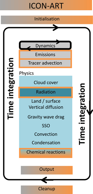
Figure 2Schematic describing the process calling structure in the climate configuration of ICON-ART 2.1.
Figure 2 shows a schematic overview of the calling strategy of subroutines with the ECHAM (climate) physics configuration. Boxes marked partly orange are shared structures between ICON and ICON-ART. Boxes with an orange frame are processes affected by ART tracer tendencies. Boxes with an orange background are ART routines. The model physics part is represented using different blue boxes. The radiation subprocess is depicted with a dark blue shaded box because the radiation process is called with a reduced frequency than other processes, in general. Chemical reactions are part of the physics routine in climate configuration but only active if ART is compiled and chemical routines are activated by a namelist parameter. All processes marked in a blue shade can have an individual calling frequency.
Most processes are treated in parallel-split mode which means that they are all computed from the same state which is provided by the dynamics. The tendencies returned by the individual processes are then summed up and applied at the end of the physics time step. Condensation constitutes an exception, as it is treated in sequential-update split mode. That is, it is also computed from the latest post-dynamics state; however, the state is immediately updated by adding the resulting tracer tendencies to the respective state variables.
It is computationally expensive to couple global tropospheric and stratospheric chemical models with global meteorological models. Therefore, it is reasonable, especially at the beginning of the development of a model like ICON-ART, to use simplified parameterisations for the description of selected chemical species. Parameterisations of chemical species can save computational costs and can give an initial overview of the general applicability of the model. In addition to parameterisations of chemical tracers, it is useful to define artificial passive tracers to investigate, e.g. transport processes in the atmosphere. An example of a passive tracer is the vortex tracer, described at the end of the following section. Further, we describe a selection of parameterisations for the simulation of chemical tracers in the atmosphere. These tracers can also be used to investigate fundamental composition–circulation feedbacks. The selection is an extension of the set of parameterisations described in Rieger et al. (2015) and Weimer et al. (2017).
4.1 Linearised ozone algorithm
Ozone is one of the most important chemical species regarding radiative heating in the middle atmosphere. Thus, ozone concentrations have to be simulated reasonably to address questions about transport processes determined by stratospheric processes (Braesicke and Pyle, 2003, 2004). ICON-ART, in its standard NWP configuration, uses monthly climatological ozone values derived from GEMS climatology (Global and regional Earth-system (Atmosphere) Monitoring using Satellite and in situ data, Hollingsworth et al., 2008). The ozone climatology used in the heating rate calculations is independent from the year of simulation. Here, we move one step forward and use the ansatz for a simplified description based on McLinden et al. (2000). This ansatz can be understood as a first-order Taylor expansion of the stratospheric chemical rates. The ozone concentration tendency is linearised with respect to the local ozone mixing ratio, temperature and overhead ozone column density. The algorithm accounts for a more realistic vertical gradient than the provided climatology. For the troposphere, we assume a constant lifetime of 30 days.
The following differential equation describes the linearised approach:
Here, ξ describes the ozone volume mixing ratio, T the temperature in the respective grid box and the overhead ozone column. The term (P−L) describes the ozone tendency, with P the production term and L the respective loss term. Climatological values are indicated with the superscript 0. The partial derivative with evaluation at the respective climatological value is marked with a subscript 0. The climatological values for P−L, and the respective derivatives are given by a look-up table.
With this ansatz, heterogeneous processes are not taken into account. The regular linearised ozone (Linoz) ansatz does not include the last term (). To address the catalytic destruction by chlorine and bromine radicals in the presence of polar stratospheric clouds, the linearised ansatz is expanded by an additional loss term. Here, τpsc represents the lifetime of ozone in the region where polar stratospheric clouds can potentially occur.
For the definition of τpsc, we follow Sinnhuber et al. (2003):
with ϑ as the solar zenith angle.
4.2 Vortex tracer
In the region of the polar stratospheric vortex, temperatures below 195 K can be observed. This low temperature regime determines the development of polar stratospheric clouds. Chlorine and bromine activation takes place on the surfaces of polar stratospheric cloud particles. This activation leads to ozone destruction. In the past, it has been observed that air parcels within the polar vortex seem to be isolated from midlatitudes (Loewenstein et al., 1989; Russell et al., 1993), because the polar vortex edge can act as a transport barrier.
To investigate processes which are relevant in the region of the stratospheric polar vortex, we introduce a polar vortex tracer in ICON-ART. The processes of interest include transport processes of air parcels from within the vortex, exchange processes at the vortex edge and mixing processes. The vortex tracer is a passive tracer with no destruction over time. This means that the tracer is only affected by transport tendencies and has no interaction with other tracers. To define the edge of the polar vortex, the first approach is to use Ertel's potential vorticity (PV), given in , which is defined as follows:
with ζ the relative vorticity in s−1, f the Coriolis parameter in s−1, ρ the air density in kg m−3, θ the potential temperature in K and z the geometric height in metres. The relative vorticity is calculated by
with the unit vector in the vertical and v the horizontal wind field in m s−1.
On a timescale of weeks and on an isentropic surface, the PV is a conserved quantity (Nash et al., 1996). The maximum in the PV gradient defines the polar vortex edge. However, as this metric shows high variations in small horizontal regions, distinct maxima cannot always be defined. Therefore, we use a second metric following Nash et al. (1996). At the polar vortex edge, the horizontal (zonal) wind component maximises and provides a surrogate for the PV gradient. In the model, the following steps are performed separately for each hemisphere: first, the PV is calculated at every grid point. Between minima and maxima of PV, a sufficient number of equidistant intervals is defined. Then, the respective geographical area enclosed by PV isolines is calculated. The maximum westerly wind relative to the area under PV isolines is derived. Multiplication of both values, the maximum and the enclosed area, gives a reasonable constraint for the polar vortex edge boundary region. The described definition holds for the location of the Northern Hemisphere polar vortex. For the Southern Hemisphere, the maximum of the easterly winds gives the constraint for the location of the edge.
At the initialisation time step, the passive tracer is initialised to one within the boundaries of the vortex. Afterwards only transport processes are in action. This provides a useful metric to investigate transport processes in the region of the polar vortex boundary.
4.3 Age of air
The characterisation of stratospheric transport from observations is difficult, because the velocity of the meridional overturning (the so-called Brewer–Dobson circulation) cannot be accessed directly. However, the efficiency of the overturning can be estimated by investigating the trends of volume mixing ratios of some long-lived trace gases (Bönisch et al., 2011; Rosenlof, 1995). One of these species is sulfur hexafluoride (SF6), which is an anthropogenically emitted chemical compound with a long lifetime of up to thousands of years (Ray et al., 2017). The increase of the middle atmosphere (up to 40 km) mixing ratio of SF6 can be assumed as quasi-linear (Maiss and Levin, 1994). In addition, SF6 has no significant chemical sink within the stratosphere. In the mesosphere, photolytic dissociation at the Lyman-α band and dissociative electron detachment should be taken into account (Ravishankara et al., 1993). With some assumptions, it is possible to calculate the age of air by using the SF6 concentration at a specific layer and horizontal location, and comparing (matching) it to past tropical tropospheric values. Thus, the age of air represents the time that an air parcel needed to travel from the tropical tropopause to this particular location in the stratosphere. In the model, a simplified procedure is followed: lower boundary conditions are updated every integration time step to simulate a linear increase of SF6 with time. The increase corresponds to an increase of the value of 1 year per year. Using the time lag technique (Reddmann et al., 2001; Schmidt and Khedim, 1991), for pressure levels above 950 hPa, one can calculate the age of air at this point by
with Δtsim is the integration time step of the model given in seconds. After initialisation, the tracer ψage in units of seconds is transported. To avoid small fluctuations, the mean age of air is taken into account for further analysis. For the final calculation, the simulated values are merged with the simulated time to get the actual age of air () in seconds:
where is the simulated time and the time of initialisation, both given in seconds.
4.4 Water vapour
Water vapour has a strong impact on the radiation budget of the atmosphere in the long-wave infrared spectrum. On the one hand, the infrared emission of water vapour leads to a cooling (loss in the thermal budget) of the atmosphere. Thus, the concentration of water vapour influences transport processes due to thermodynamic induced changes in the wind field. On the other hand, transport processes affect water vapour concentrations. The investigation of water vapour in models and observation allows studying global circulation patterns (Kley et al., 2000). The amount of water vapour entering the stratosphere depends on the temperature within the tropical tropopause layer (TTL). Above, the Brewer–Dobson circulation drives the upward transport in the tropics. Below, convective fluxes and slow ascend in the TTL determine vertical transport. The process of “freeze-drying” leads to dry air parcels entering the stratosphere, because ice crystals sediment out (Brasseur and Solomon, 2006). This process is included in the microphysical schemes of the NWP and the climate physics. Methane oxidation is a chemical source for stratospheric water vapour. Higher up, methane oxidation is a chemical source for stratospheric water vapour. However, the photodissociation of water, mainly located in the mesosphere, is an important sink for water vapour in the atmosphere.
We follow Dethof (2003) by using the following parameterisation:
with the lifetime of methane in seconds, p the pressure and . Based on Brasseur and Solomon (2006), the lifetime of water vapour () due to photodissociation can be calculated by
Taking both terms of production and loss into account, the volume mixing ratio of water vapour at time step t+Δtsim can be calculated by
with in mol mol−1 as the methane tracer of ICON-ART.
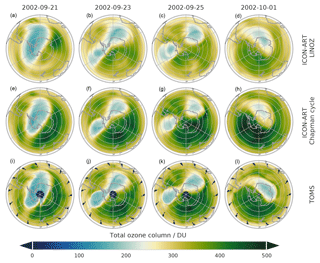
Figure 3Antarctic total ozone column (DU) for a time sequence starting on 21 September 2002 finishing 1 October 2002 (left to right). Daily averages for two ICON-ART simulations for the Linoz chemistry scheme (a–d) and for the extended Chapman cycle chemistry (e–h). Total Ozone Mapping Spectrometer (TOMS) observations are shown in panels (i–l). The model was initialised on 20 September 2002.
Studies have shown that observed mean-annual cooling trends in the tropical tropopause are larger than shown by model simulations, e.g. Shine et al. (2003). It can be seen that the large-scale dynamics in the Earth's atmosphere, tropical tropopause temperatures and lower stratospheric water vapour are closely linked to each other by complex feedback processes. By using the parameterisations described above in ICON-ART, we want to account for these important feedback mechanisms in a simple but reasonable way. To investigate the feedback processes of the ART water vapour tracer (including radiation), only the tendencies from the methane oxidation and photodissociation are taken into account. At every model time step, the water vapour mass mixing ratio is set to the value of the qv tracer, which is affected by the microphysics routines of ICON. The qv tracer is the standard water vapour tracer of ICON. Within the ICON-ART routine, the tendency due to methane oxidation and photodissociation can be added. In the last step, qv is set to the value of . The standard tracer qv is overwritten before other processes like radiation or microphysics are active.
Here, we use ICON-ART and its new tracer framework with the NWP and the climate physics configuration in different applications. First, we discuss a stratospheric hindcast experiment based on the ICON NWP configuration, focusing on different chemistries (Sect. 5.1). Second, we show some climatological applications based on the ICON climate physics configuration, illustrating the impact of chemical composition feedbacks.
5.1 Ozone and vortex tracer
In 2002, an unusual split of the ozone hole was observed on 22 September 2002 and described by Newman and Nash (2005). The initiation of the splitting process is not fully understood yet. The split of the ozone hole had no chemical reason; instead, it is a dynamical change controlling atmospheric composition and in particular ozone distributions. Several studies, e.g. Matsuno (1971), have shown that a vortex split event can be caused by atmospheric interactions with upward propagating planetary waves. Sinnhuber et al. (2003) pointed out that the major stratospheric warming occurred far earlier than the normal final warming at the end of the ozone hole season. With ICON-ART, we are able to study the vortex split event of 2002 in a hindcast. First, we want to discuss the total ozone column simulated with ICON-ART. For the setup of the experiment, we use reanalysis data from the European Centre for Medium-Range Weather Forecasts (ECMWF) – ERA-Interim (Dee et al., 2011) to initialise the meteorological variables (e.g. pressure, temperature, water vapour and horizontal wind fields). The hindcast is initialised on 20 September 2002, 00:00 UTC. The chosen grid is R2B6, corresponding to an approximate horizontal grid spacing of 40 km (Zängl et al., 2015). The model top is at 75 km with 90 vertical levels. The integration time step is 240 s, and the output time step is every hour. The simulated ozone column, interpolated on a regular latitude–longitude grid with a resolution of 0.5∘, is shown in Fig. 3. The four columns show daily means of total ozone for the respective dates. The mean is taken over all 24 output steps starting at 00:00 UTC. For the initial values of ozone, the ERA-Interim data are used analogous to the meteorological data. The ozone hindcasts are performed with two different schemes: the modified Linoz scheme as described in Sect. 4.1 and a gas-phase algorithm (the extended Chapman cycle) with reactions described in Table 2.4. For the comparison between simulations and measurements, we are using satellite observations from the Total Ozone Mapping Spectrometer (TOMS) instrument (TOMS Science Team, 2016).
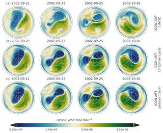
Figure 4Passive and active ozone tracers (mol mol−1) at 50 hPa over Antarctica. Daily averages for two ICON-ART simulations for the Linoz chemistry scheme (a) and for the extended Chapman cycle chemistry (b) and the passive tracer (c) are shown.
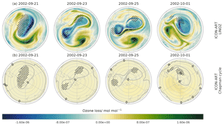
Figure 5Difference of the passive and active ozone tracers (mol mol−1) at 50 hPa over Antarctica. Daily averages are shown for two ICON-ART simulations for the Linoz chemistry scheme (a) and for the extended Chapman cycle chemistry (b). For the loss rate of the Chapman cycle, the zero contour line is added. Shaded areas indicate temperature regions below 195 K.
A total of 5 days after initialisation, the represented horizontal geometry of the total ozone column in both ICON-ART simulations was slightly different in comparison to the satellite observations. After more than 10 days of simulation, the shape of the vortex was still in good agreement with satellite observations. Within the polar vortex, the total ozone column reached values of about 200 DU in both, ICON-ART simulations and the satellite observations. At the end of the simulation, on 1 October 2002, the largest difference between the extended Chapman cycle simulation, using the full gas-phase algorithm, and the simplified Linoz simulation was found at 70∘ S, 120∘ W, outside of the polar vortex. The total ozone column reached values of 450 DU and above for the extended Chapman cycle simulation. For the Linoz simulation, ozone destruction was slightly higher and values up to 400 DU were reached. The comparison to the TOMS observation shows that this minimum fits to observation. However, the horizontal pattern slightly differs. The observation also shows small areas with up to 420 DU.
In order to illustrate the differences between the two idealised simulations (parameterised using Linoz; gas-phase chemistry only with an extended Chapman cycle), the total contribution of chemical tendencies is depicted in Figs. 4 and 5. We are using the differences between a passive (no chemical changes after initialisation) ozone tracer and the chemical ozone tracers for Linoz and extended Chapman cycle chemistry. The difference represents the chemical ozone loss.
The passive and the chemical ozone tracers are initialised identically. Technically, this is ensured by declaring the ozone tracers to be the same type as the chemical tracer but without chemical interactions. The corresponding XML entry can be found in Appendix A1. In Fig. 5, at 70∘ S, 120∘ W, on 1 October 2010, ozone loss is dominated by chemical loss. Ozone losses are higher in that region. The passive tracer, which is only affected by dynamical tendencies, has higher values than the chemical tracers; thus, ozone has been depleted by the chemical mechanisms. The maximum difference between passive and chemical tracers is up to 10 times higher for the Linoz simulation than for the extended Chapman cycle. For visualisation purposes, the contour line representing no loss (0 mol mol−1) is added. This is to be expected, because the initial ozone distribution is not equilibrated with respect to the Linoz reference state (causing large tendencies) and we do not consider additional loss terms by heterogeneous processes or halogens in the extended Chapman cycle chemistry (limiting the range of chemical tendencies). However, we can focus on the general spatial structures and how transport has modified ozone distributions. Inside the polar vortex, on 1 October 2002, we model ozone production for both simulations. The chemical tracer in both simulations is increased with respect to the passive one. The increase is higher in the Linoz simulation than in the extended Chapman cycle. This implies that temperatures in that region are not low enough to trigger the heterogeneous destruction of ozone in the Linoz scheme. Outside the polar vortex, mainly on 25 September, high values of ozone loss can be observed for the Linoz simulation but not for the extended Chapman cycle. This is also caused by the difference in addressing heterogeneous destruction. Within the Linoz scheme, the loss term has been triggered and we can observe additional ozone loss. This feature is missing for the extended Chapman cycle chemistry.
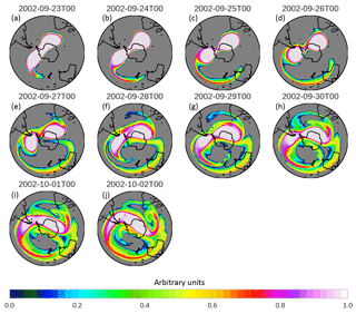
In Fig. 6, the temporal evolution of the passive vortex tracer is depicted. The colour coding gives the values of the vortex tracer at an interpolated pressure level of 30 hPa at midnight on the given date. Again, the date of initialisation is chosen to be 20 September 2002 and within the boundaries of the vortex; the tracer is set to a value of 1. Here, only transport takes place. The horizontal spreading of the vortex tracer depicts the dynamical evolution of the vortex in the Southern Hemisphere. The horizontal spreading and steep tracer gradients correspond to the horizontal distribution of the total ozone column in Fig. 3. At the day of initialisation, the vortex is still intact, but in the following days the first observed major stratospheric warming in the Southern Hemisphere, e.g. (Newman and Nash, 2005), occurs. The massive outflow of vortex air masses, beginning on 24 September 2002, can be visualised by the vortex tracer distributions. This outflow is correlated to the increased dynamical impact on the vortex integrity. The vortex split occurred on 26 September 2002. The structure, represented by the spatial distribution of the vortex tracer, is nearly separated. On this day, the northernmost latitude of 30∘ S is reached by a vortex filament. The vortex tracer allows to define regions of isolated air masses within the vortex, thus providing an insight into the chemical composition changes that are least affected by diffusion and mixing (e.g. McKenna et al., 2002 or Konopka et al., 2005).
5.2 Feedback of ozone on radiation
In the previous section, we have shown that the Linoz configuration of ICON-ART provides good hindcasts on days to weeks. The limitation that the initial state should be equilibrated, mentioned above, does not matter after a spin-up period. Here, we will extend the time horizon considered to decadal integrations. In addition, we will illustrate how the optional composition of tracers with radiation feedback affects the system. With the flexible tracer structure, the user has the ability to switch on the radiative feedback by the tag
<feedback> 1 </feedback>.
Thus, no changes in the code have to be made by the user. Only the XML file has to be changed.
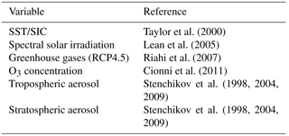
The ICON-ART simulation is configured as an AMIP (Atmospheric Model Intercomparison Project) like experiment (Gates et al., 1999). The boundary conditions used are summarised in Table 2. We set up two experiments on the R2B4 grid which corresponds to an effective horizontal grid spacing of 160 km. The integration time step is chosen to be 600 s. Output is written every 3 days and interpolated onto predefined pressure levels, corresponding to the standard ERA-Interim pressure levels. The first experiment uses an ozone climatology with monthly mean values based on Cionni et al. (2011). This simulation is called “control”. The feedback simulation uses the interactive ozone as well as the additional tendencies on water vapour, shown in Sect. 4.4. For all following diagnostics and discussions, the same two simulations are used. The results of the complete integration from 1979 to 2009 are found in Appendix B. In the following, analysis of the time span from 1990 to 2009 is shown. This avoids possible differences arising from changes in ozone depleting substances from 1979 to 1990 that are not considered in Linoz with time-invariant look-up tables.
Taylor et al. (2000)Lean et al. (2005)Riahi et al. (2007)Cionni et al. (2011)Stenchikov et al. (2004, 2009, 1998)Stenchikov et al. (2004, 2009, 1998)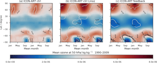
Figure 7Monthly averaged zonal means of ozone (kg kg−1) at 50 hPa (shown twice) for the period from 1990 to 2009 (shaded). Contour lines represent the standard deviation of the monthly means. (a) Ozone climatology as used in the control simulation; (b) non-interactive Linoz ozone; (c) interactive Linoz ozone.
Figure 7 shows the climatological ozone distribution at a pressure level of 50 hPa. Monthly averaged zonal means of ozone for the period of 1990 to 2009 are plotted twice. Figure 7a shows the ozone used in the control run (ctrl) (Table 2). Figure 7b shows the modelled ozone of the non-interactive Linoz simulation, where modelled temperatures are the same as in the control run. Figure 7c shows the temporal evolution of the zonal mean ozone in the feedback simulation. Additionally, contour lines are representing the interannual standard deviations of ozone in all panels. The black contour line represents a standard deviation of kg kg−1. Brighter colours present higher values of standard deviation with a spacing of kg kg−1.
A striking difference in the three ozone distributions shown in Fig. 7 is the duration of the ozone hole period indicated by the area that is shaded in dark blue. Modelled ozone (Fig. 7b, c) shows a much longer duration than the assumed background climatology. In addition, the duration of the ozone hole period increases slightly for the interactive integration. This is caused by the feedback of the modelled ozone, calculated with the Linoz parameterisation under consideration of the correction term for a shorter ozone lifetime due to the presence of polar stratospheric clouds. From October to December, very low ozone concentrations of about kg kg−1 can be seen in the panel for the non-interactive Linoz ozone (Fig. 7b). For the feedback simulation, low ozone concentrations in the Southern Hemisphere, in conjunction with low temperatures, occur until the end of spring. The feedback process stabilises the Southern Hemisphere polar vortex, prolonging its lifetime by delaying the final warming. The default climatology of the ICON-ART control simulation does not represent very low values of ozone concentrations. This misrepresentation has also been discussed by, e.g. Arblaster et al. (2014). Here, the authors point out that most models that are using a prescribed ozone climatology tend to underestimate the Antarctic ozone depletion. Thus, modelled ozone values are higher than indicated by observations between 1979 and 2007 (Hassler et al., 2013). Taking the standard deviation into account, the characteristics of the AMIP ozone climatology (Cionni et al., 2011) become clearer. The contour lines represent a semicircle each winter in the Southern Hemisphere that is aligned with the ozone concentration gradients. This symmetric and coherent pattern of the ozone minimum is most likely not a very realistic representation of variability on top of an ozone hole that is not deep enough. The standard deviation isolines for the modelled ozone are different and intersect the isolines of ozone concentrations, with higher variabilities at later times in the ozone hole period.
We note that the standard deviations shown in Fig. 7 should be interpreted differently between the control and feedback simulations of ICON-ART. This is due to the fact that in the control simulation a time-varying background climatology is used that has an imposed long-term trend, whereas in the feedback simulation, no trend is imposed, and the internal variability of ICON-ART is the main component of the ozone variability. To illustrate this difference, we summarise the results of a time series decomposition in Table 3.
We use the time series of the 60∘ S zonal mean total ozone column of both ICON-ART simulations. For comparison, we analyse TOMS observational data (TOMS Science Team, 2016), also at 60∘ S. The chosen latitude allows a continuous time series analysis. We separate the time series of the ICON-ART simulations in two periods: 1980 to 1997 and 1997 to 2009. The ICON-ART control simulation shows an ozone decline for the earlier period and a small ozone increase for the later period (by construction of the background climatology). The feedback simulation shows no pronounced trend (as expected; see above) in particular during the later period. Note that the RMSE (root mean square error) is higher in both periods for the feedback simulation compared to the ICON-ART control simulation. The higher RMSE is induced by substantial year-to-year meteorological variability. Both model time series can be compared to the shorter TOMS on NIMBUS 7 time series (1997 to 2005).
Table 3Results of the time series analysis for different time domains at 60∘ S for the ozone total column. Results for both ICON-ART simulations and TOMS observation are shown. The early period is from 1980 to 1997 and the late period is from 1997 to 2009 (to 2005 for TOMS on NIMBUS 7). The the annual cycle (AC) minimum and maximum anomalies are derived from the full time series.

5.3 Temperature changes due to ozone feedback
In the previous section, we have shown that with the change to an interactive representation of ozone the duration of the southern polar vortex is increased. Here, we provide more details on the zonal mean temperature distributions in the control and feedback simulations.
The direct impact of ozone, already mentioned in Sect. 5.2, is also displayed in the seasonal variation of the zonal mean temperatures; see Fig. 8.
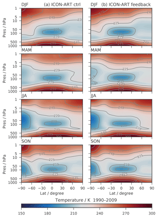
Figure 8Latitude–height cross sections of seasonal and zonal mean temperature (K) for ICON-ART simulations from 1990 to 2009. (a) Control run; (b) feedback simulation.
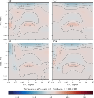
Figure 9Latitude–height cross sections of seasonal and zonal mean temperature differences (K) for control minus feedback simulation, as shown in Fig. 8.
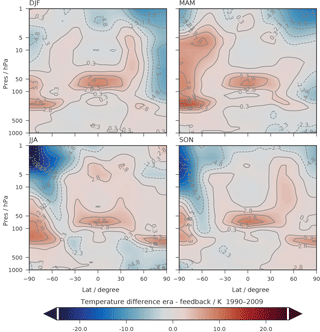
Figure 10Latitude–height cross sections of seasonal and zonal mean temperature differences (K) for ERA-Interim minus feedback simulation.
In the Northern Hemisphere winter (DJF), temperatures of 210 K are reached between 100 and 10 hPa in the tropics. For the season of June–July–August (JJA), the temperature minimum in the tropics is at 100 hPa with temperatures as low as 200 K in both ICON-ART simulations. In the Southern Hemisphere winter, ICON-ART control reaches temperatures of about 200 K and ICON-ART feedback temperatures lower than 195 K. The Northern Hemisphere summer is represented by temperatures higher than 260 K above 5 hPa.
Figure 9 shows the difference between control and feedback runs. In the Southern Hemisphere winter, the effect described in Sect. 5.2 can be observed. Due to the lower polar vortex temperature, differences up to 5 K occur. The control run shows warmer temperatures in the southern polar region (below 20 hPa). Above this altitude, the feedback run is warmer than the control run. This is due to the different ozone distributions in the Southern Hemisphere winter. Within the tropical stratosphere, temperature differences of about 2.8 K can be seen. The differences of zonal and seasonal mean temperatures between ERA-Interim and the ICON-ART feedback simulation are shown in Fig. 10. The feature of a long-lasting Southern Hemisphere polar vortex is present as well, seen in high temperature differences of up to 20 K from September to November (SON). In general, the ICON-ART control simulation shows warmer temperatures than the ICON-ART feedback simulation, except for high altitude ranges above 5 hPa.
The general structure is comparable to the results shown in the comparison studies of ECHAM5 (Roeckner et al., 2006). The difference between ERA-Interim and ICON-ART is increased in the Southern Hemisphere stratosphere. Nevertheless, the representation of the polar vortex seems to be more realistic in the ICON-ART feedback simulation than in the control simulation. In the vertical region around 50 hPa, the difference between ERA-Interim and the feedback simulation is about 15 to 20 K in the Southern Hemisphere and below 8 K in the tropics.
5.4 Zonal wind fields
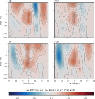
Changes in temperature due to radiative feedback effects of ozone are also affecting the zonal wind structure. The zonal mean zonal wind is shown in Fig. 11. The left column shows the seasonal mean of the control ICON-ART simulation and the right column the feedback simulation. In both simulations, a strong eastward zonal wind with wind speeds up to 60 m s−1 is reached in the Southern Hemisphere winter (JJA). The wind speed patterns in the tropical stratosphere also match the seasonal mean analysis.
Figure 12 shows the differences between the ERA-Interim and the results of the ICON-ART feedback simulation. Strong differences in the stratospheric zonal wind can be seen in the Northern Hemisphere winter. Here, ERA-Interim shows values up to 25 m s−1 lower than in the ICON-ART simulation. Between 30 and 60∘ N latitude above 20 hPa, the sign of the differences changes. Here, we observe stronger zonal wind speeds than in ERA-Interim. The overall patterns are similar to the differences shown in Roeckner et al. (2006).
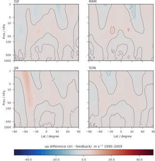
Figure 11Latitude–height cross sections of seasonal and zonal mean zonal wind differences (m s−1) for ICON-ART simulations from 1990 to 2009.
5.5 Water vapour
Here, we focus on the atmospheric water vapour tape recorder in ICON-ART. An atmospheric tape recorder can be defined as the vertical propagation of an anomaly that varies periodically in time with a tropospheric source (Gregory and West, 2002). The temporal and vertical distribution of the tropical stratospheric water vapour is a prominent example for an atmospheric tape recorder signal. The simulated stratospheric water vapour depends strongly on the temperatures that are encountered by an air parcel containing water vapour that is transported vertically from the troposphere upwards towards and through the tropopause (Schoeberl et al., 2012). The quantitative link between variations of tropical tropopause temperatures over decades and their influence on water vapour transfer into the stratosphere is still not fully understood (Rosenlof and Reid, 2008). It has been shown that stratospheric water vapour can have a strong impact on stratospheric climate (de F. Forster and Shine, 1999). Thus, the study of the water vapour tape recorder is an important tool for the further understanding of large-scale transport processes and climate change linkages.
The tape recorder anomalies are calculated relative to the annual mean water vapour in the tropics (5∘ N–5∘ S). For this study, we use the water vapour tracer, qv. This tracer is the standard tracer of ICON itself. It is used in the radiation scheme and is not only transported but is also affected by the microphysical schemes. As in the previous section, ozone is calculated with the Linoz scheme and used interactively. The additional water tendencies by methane oxidation and photolysis is also included in the stratospheric water budget.
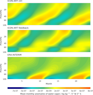
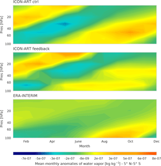
Figure 13Tropical (5∘ N–5∘ S) water vapour anomalies as monthly mean deviations (plotted twice) from the annual mean, averaged from 1990 to 2009, as a function of months and altitude.
Figure 13 shows the stratospheric tape recorder. For the analysis, the years 1990 to 2009 are taken into account. We compare the ICON-ART results with the water vapour product from ERA-Interim. The calculated mean ERA-Interim tape recorder is shown in the bottom panel of Fig. 13.
The tape recorder signal for the ICON-ART control simulation shows lower values of anomalies down to kg kg−1 in comparison to the feedback simulation (Fig. 13). For ERA-Interim, anomalies up to kg kg−1 are diagnosed from February to June in the pressure range of 100 to 50 hPa.
The anomalies in the feedback simulation show higher absolute values. The dry anomalies in the control simulation, between April and June, are decreased in the feedback simulation. In addition, the positive (wet) anomalies from June to December, between 60 to 20 hPa, are decreased in the feedback simulation. The water vapour tape recorder shows less pronounced dry anomalies in the tropical stratosphere in the feedback simulation due to the additional source of water vapour by methane oxidation. Additionally, the analysis of the water vapour tape recorder is consistent with the results of the temperature differences, as seen in Fig. 9. Due to lower tropical tropopause temperatures in the feedback simulation, less water can enter the lower stratosphere. The annual mean temperature difference (not shown) shows that the control simulation is up to 2.8 K warmer than the feedback simulation between 100 and 50 hPa, in the tropics. The results correspond with the freeze-drying hypothesis explained above. In general, monthly mean anomalies are attenuated in the feedback simulation compared to the simulation using the standard ozone climatology, with in particular the winter months being more similar to ERA-Interim. Focusing on the strong positive anomaly between 100 and 50 hPa, from May to August, the explanation from above has to be extended. The annual mean shows a cold bias of the tropical tropopause. However, referring to Fig. 9, one can see that, for that time span, the sign of temperature changes. In the feedback simulation, higher temperatures in the tropical tropopause are reached. Thus, more water vapour can enter the stratosphere which is a possible explanation for the strong positive anomaly.
The tape recorder signal of ERA-Interim shows a maximum amplitude in the lower stratosphere between 100 and 60 hPa. In the ICON-ART control simulation, the lower stratospheric amplitude of the water vapour tape recorder is already smaller. With interactive ozone and water vapour, as in the ICON-ART feedback simulation, the lower stratospheric amplitude is attenuated further. However, a relative maximum above 20 hPa occurs. This is likely the result of an overestimated water vapour tendency provided by the methane oxidation, because methane is biased slightly high in the feedback simulation.
The slope of the latitude–height water vapour anomalies is nearly unchanged between non-interactive and interactive integrations. Thus, the velocity of the upward transport is largely unaffected by the inclusion of the radiative feedback. The result of both ICON-ART simulations in comparison to ERA-Interim is similar to the results presented in Jiang et al. (2015). Here, the authors combined measurements and simulations of water vapour from the Microwave Limb Sounder (MLS), GMAO Modern-Era Retrospective Analysis for research and Applications in its newest version (MERRA-2) and ERA-Interim and used them for a comparison of the water vapour tape recorder behaviour. The upward transport above the tropical tropopause of ERA-Interim is found to be faster than the transport diagnosed from MLS measurements. Thus, in the current configuration, ICON-ART produces similar ascent rates to ERA-Interim, which are likely faster than observed.
We have shown that the change between interactive and non-interactive integrations with respect to tropical ascent rates is small. However, some changes are clearly detectable and the important relationship between the tropical tropopause minimum temperatures and water vapour concentrations is qualitatively captured by the ICON-ART system. More comprehensive climate studies are in preparation.
5.6 Age of air
For the simulation of the age of air, we use the same setup as described in Sect. 5.3. As all other diagnostics, the age of air tracer is interpolated on a regular latitude–longitude grid with a horizontal resolution of on predefined pressure levels.
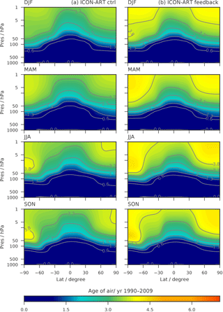
Figure 14Latitude–height cross sections of seasonal and zonal mean ages of air (year) for ICON-ART simulations from 1990 to 2009. (a) Control run; (b) feedback simulation.
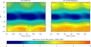
Figure 15Monthly averaged zonal means of age of air (year) at 50 hPa (shown twice) for the period from 1990 to 2009 (shaded). Contour lines represent the standard deviation of the monthly means. (a) Control run; (b) feedback simulation.
The tracer is initialised as described in Sect. 4.3. The control (ctrl) experiment is a simulation in which water vapour and ozone calculated within ICON-ART have no impact on the calculation of radiation. In the second experiment (feedback), the altered ozone and water vapour distributions of ICON-ART are coupled to the radiation routine. The first 11 years of each simulation are excluded in the analysis to prevent spin-up effects contaminating the result.
The ICON-ART modelled age of air is depicted in Fig. 14. The diagnostic of age of air can be seen in this case study as an important tool to analyse the feedback processes of greenhouse gases on transport processes in the Earth's atmosphere. It can be seen that the mean age of air is younger; thus, the upward transport has been faster in the control simulation. Due to upwelling transport processes in the tropics, the youngest air masses can be found there. The polar regions show the occurrence of older air masses up to an age of 4 years in both simulations. The asymmetry between Southern Hemisphere and Northern Hemisphere, induced by faster circulations in the Southern Hemisphere (Mahieu et al., 2014), is also well captured. One can clearly see the impact of ozone and water vapour on radiation and thus on transport processes. The age of air in the feedback simulation is up to 6 months older than the control simulation. Figure 15 shows the climatological mean age of air, in the same representation as shown in Fig. 7. Here, the temporal and zonal means of the age of air from 1990 to 2009 are taken at an altitude of 50 hPa. The standard deviation from the mean is represented by the contour lines. These lines represent the interannual variability. The absolute mean age of air is higher for the feedback simulation on both hemispheres. The band of low values in the tropics is narrowed for the feedback simulation. The values of standard deviation are comparable. However, in the region of the Southern Hemisphere polar vortex, from October to January, the standard deviation is higher for the feedback than for the control simulation. Since the polar vortex is stabilised by the ozone feedback, a different dynamical situation can be observed, influencing the interannual variability of the age of air. In comparison to other studies, which focus on other time spans (Brasseur and Solomon, 2006; Engel et al., 2009; Haenel et al., 2015; Stiller et al., 2012), ICON-ART shows an age of air which is too young compared to observations. But this behaviour has also been observed in other studies with different models, as described in, e.g. Monge-Sanz et al. (2007) or Hoppe et al. (2014). With this diagnostic, the general representation of stratospheric transport processes can be investigated further.
We present a new flexible tracer framework developed for ICON-ART. The next-generation model ICON-ART can be used for many different applications currently ranging from forecasting to climate simulations. ICON is used for LES simulations, operationally for numerical weather forecasting and for climate simulations. All three application areas have very different demands in terms of model configurations, including the set of tracers and tracer interactions to be simulated. For future studies using ICON-ART, a fast adaption of the selected tracers and interactions to the experimental requirements is of high importance. With our new flexible tracer framework, tracers can be added and configured without any changes to the model source code. This allows users to easily perform complex model experiments. In a forward-thinking manner, we also provide the option to extend the existing tracer structure and submodule awareness of tracer subsets. Within the scope of the paper, we demonstrate the tracer framework and its applicability for a range of simulations. We present one hindcast case study and AMIP-type climate integrations.
In the first instance, we included a parameterised chemistry (Linoz) and a gas-phase chemistry (extended Chapman cycle) into the NWP configuration of ICON-ART. With this setup, we perform a successful hindcast experiment of the ozone hole split in the year 2002 and characterise the (chemical) ozone changes during the hindcast period. Using a diagnostic vortex tracer, we can identify the vortex remnants that are least influenced by chemistry. Results are consistent with expectations and previous work and illustrate the ability of the ICON model to produce a good stratosphere forecast on timescales of days to weeks. In this situation, dynamics is driving the ozone distribution and the spatial patterns correspond well to observations. However, ozone amounts differ between the two different chemical mechanisms. The setup can be easily extended by additional chemical reactions and diagnostic tracers.
In the second instance, we include a parameterised chemistry (Linoz), a methane oxidation scheme and a diagnostic tracer (age of air) into a climate configuration of ICON-ART and perform AMIP-type integrations. We perform decadal non-interactive and interactive integrations and compare the performance of both simulations to each other and to ERA-Interim. For the interactive integration, we couple ozone and water vapour to the radiation. In the interactive simulation, the ozone hole season is extended, the tropical upwelling is only weakly affected, and the overturning circulation as measured by the Brewer–Dobson circulation shows a Northern Hemisphere age increase up to 1.5 years. The base climatology of ICON is not affected by ART in the non-interactive simulation. In the interactive simulation, some changes to the climatology of temperature and winds occur; none of the changes are detrimental to the model, and some are even beneficial.
For all experiments, no changes in the ART source code were necessary to change from NWP simulations to climate integration. Only the XML file differs between the full gas-phase (extended Chapman cycle) simulation and the parameterised (Linoz) one. This paper demonstrates the flexibility of the new tracer framework for ICON-ART, which suits the demands of a large variety of different applications ranging from NWP to climate integrations.
Currently, the legal departments of the Max Planck Institute for Meteorology (MPI-M) and the DWD are finalising the ICON licence. If you want to obtain ICON-ART, you will first need to sign an institutional ICON licence, which you will get by sending a request to icon@dwd.de. In a second step, you will get the ART licence by contacting Bernhard Vogel (bernhard.vogel@kit.edu). Versions are controlled by GIT repositories, and a tar ball of the latest official release is provided to the licensee.
A1 Ozone and vortex tracer – NWP experiment
Passive tracers
<?xml version="1.0" encoding="UTF-8"?>
<!DOCTYPE tracers SYSTEM "tracers.dtd">
  <tracers>
      <passive id="TR_vortex">
        <mol_weight type="real">1.000E+0</mol_weight>
            <lifetime type="real">25920000</lifetime>
         <transport type="char"> ON </transport>
         <unit type="char">none</unit>
      </passive>
 </tracers>
Chemical tracers – Linoz
<?xml version="1.0" encoding="UTF-8"?>
<!DOCTYPE tracers SYSTEM "tracers.dtd">
   <tracers>
      <chemical id="TRO3">
         <tag001 type="char">chemtr</tag001>
         <mol_weight type="real">4.800E-2</mol_weight>
         <lifetime type="real">259200</lifetime>
         <transport type="char"> stdchem </transport>
         <init_mode type="int"> 1 </init_mode>
         <init_name type="char">O3</init_name>
         <unit type="char">mol mol-1</unit>
         <lfeedback type="int"> 0 </lfeedback>
      </chemical>
      <chemical id="TRO3_pas">
         <tag001 type="char">chemtr</tag001>
         <mol_weight type="real">4.800E-2</mol_weight>
         <lifetime type="real">2592000000000</lifetime>
         <transport type="char"> stdchem </transport>
         <init_mode type="int"> 1 </init_mode>
         <init_name type="char">O3</init_name>
         <unit type="char">mol mol-1</unit>
         <lfeedback type="int"> 0 </lfeedback>
      </chemical>
   </tracers>
Selection of chemical tracers for the extended Chapman mechanism (not all tracers are shown)
<?xml version="1.0" encoding="UTF-8"?>
<!DOCTYPE tracers SYSTEM "tracers_gp.dtd">
  <tracers>
      <chemical id="N2O">
          <tag001 type="char">full</tag001>
          <mol_weight type="real">44.02E-3</mol_weight>
          <transport type="char">stdchem</transport>
          <number type="int"> 1 </number>
          <init_mode type="int">0</init_mode>
          <unit type="char">mol mol-1</unit>
          <init_type="char">N2O </init_name>
      </chemical>
      <chemical id="N2O5" >
          <tag001 type="char">full</tag001>
          <mol_weight type="real">108.02E-3</mol_weight>
          <transport type="char">stdchem</transport>
          <number type="int"> 2 </number>
          <init_mode type="int">0</init_mode>
          <unit type="char">mol mol-1</unit>
          <init _ype="char">N2O5 </init_name>
      </chemical>
      <chemical id="HO2">
          <tag001 type="char">full</tag001>
          <mol_weight type="real">33E-3</mol_weight>
          <transport type="char">stdchem</transport>
          <number type="int"> 3 </number>
          <init_mode type="int">0</init_mode>
          <unit type="char">mol mol-1</unit>
          <init_name type="char">HO2 </init_name>
      </chemical>
      <chemical id="H2O" >
           <tag001 type="char">full</tag001>
           <mol_weight type="real">18E-3</mol_weight>
           <transport type="char">stdchem</transport>
           <number type="int"> 4 </number>
           <init_mode type="int">0</init_mode>
           <unit type="char">mol mol-1</unit>
           <init_name type="char">H2O </init_name>
      </chemical>
      <chemical id="NO">
          <tag001 type="char">full</tag001>
          <mol_weight type="real">30.01E-3</mol_weight>
          <transport type="char">stdchem</transport>
          <number type="int"> 5 </number>
          <init_mode type="int">0</init_mode>
          <unit type="char">mol mol-1</unit>
          <init_name type="char">NO </init_name>
      </chemical>
      <chemical id="NO3">
          <tag001 type="char">full</tag001>
          <mol_weight type="real">62.01E-3</mol_weight>
          <transport type="char">stdchem</transport>
          <number type="int"> 6 </number>
          <init_mode type="int">0</init_mode>
          <unit type="char">mol mol-1</unit>
          <init_name type="char">NO3 </init_name>
      </chemical>
      <chemical id="O1D">
          <tag001 type="char">full</tag001>
          <mol_weight type="real">16E-3</mol_weight>
          <transport type="char">stdchem</transport>
          <number type="int"> 12 </number>
          <iconv type="int">1</iconv>
          <iturb type="int">1</iturb>
          <init_mode type="int">0</init_mode>
          <init_number type="int">0</init_number>
          <unit type="char">mol mol-1</unit>
      </chemical>
</tracers>
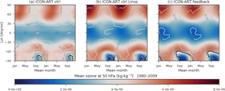
Figure B1Monthly averaged zonal means of ozone (kg kg−1) at 50 hPa (shown twice) for the period from 1980 to 2009 (shaded). Contour lines represent the standard deviation of the monthly means. (a) Ozone climatology as used in the control simulation; (b) non-interactive Linoz ozone; (c) interactive Linoz ozone.
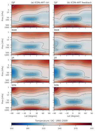
Figure B2Latitude–height cross sections of seasonal and zonal mean temperatures (K) for ICON-ART simulations from 1980 to 2009. (a) Control run; (b) feedback simulation.
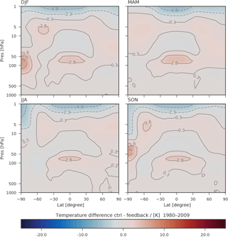
Figure B3Latitude–height cross sections of seasonal and zonal mean temperature differences (K) for control minus feedback simulation, as shown in Fig. 8.
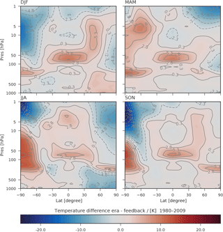
Figure B4Latitude–height cross sections of seasonal and zonal mean temperature differences (K) for ERA-Interim minus feedback simulation.
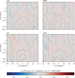
Figure B5Latitude–height cross sections of seasonal and zonal mean zonal wind differences (m s−1) for ICON-ART simulations from 1980 to 2009. (a) Control run; (b) feedback simulation.
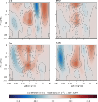
Figure B6Latitude–height cross sections of seasonal and zonal mean zonal wind differences (m s−1) for ERA-Interim minus feedback simulation.
| AMIP | Atmospheric Model Intercomparison Project |
| ART | Aerosols and Reactive Trace gases |
| COSMO | Consortium for Small-scale Modeling |
| DWD | German Weather Service |
| ECHAM | EC(MWF) HAM(burg) |
| ECMWF | European Centre for Medium-Range Weather Forecasts |
| HD(CP)2 | High Definition Clouds and Precipitation for advancing Climate Prediction |
| KPP | Kinetic PreProcessor |
| MECCA | Module Efficiently Calculating the Chemistry of the Atmosphere |
| MLS | Microwave Limb Sounder |
| NWP | Numerical weather prediction |
| RMSE | Root mean square error |
| SIC | Sea ice cover |
| SST | Sea surface temperature |
| SSO | Subgrid-scale orography |
| TOMS | Total Ozone Mapping Spectrometer |
| TTL | Tropical tropopause layer |
The authors declare that they have no conflict of interest.
This work was performed on the computational resource ForHLR II funded by the
Ministry of Science, Research and the Arts Baden-Württemberg and DFG
(Deutsche Forschungsgemeinschaft).
The
article processing charges for this open-access
publication
were covered by a Research
Centre of the Helmholtz
Association.
Edited by: Gerd A.
Folberth
Reviewed by: Johannes Bieser and one anonymous
referee
Aho, A. V., Kernighan, B. W., and Weinberger, P. J.: The AWK programming language, Addison-Wesley Longman Publishing Co., Inc, 1987. a
Arblaster, J. M., Gillett, N. P., Calvo, N., Forster, P. M., Polvani, L. M., Son, W. S., Waugh, D. W., Young, P. J., Barnes, E. A., Cionni, I., Garfinkel, C. I., Gerber, E. P., Hardiman, S. C., Hurst, D. F., Lamarque, J.-F., Lim, E.-P., Meredith, M. P., Perlwitz, J., Portmann, R. W., Previdi, M., Sigmond, M., Swart, N. C., Vernier, J.-P., and Wu, Y.: Stratospheric ozone changes and climate, chapt. 4, in: Scientific Assessment of Ozone Depletion: 2014, Global Ozone Research and Monitoring Project – Report No. 55, World Meteorological Organization, Geneva, Switzerland, 2014. a
Baklanov, A., Schlünzen, K., Suppan, P., Baldasano, J., Brunner, D., Aksoyoglu, S., Carmichael, G., Douros, J., Flemming, J., Forkel, R., Galmarini, S., Gauss, M., Grell, G., Hirtl, M., Joffre, S., Jorba, O., Kaas, E., Kaasik, M., Kallos, G., Kong, X., Korsholm, U., Kurganskiy, A., Kushta, J., Lohmann, U., Mahura, A., Manders-Groot, A., Maurizi, A., Moussiopoulos, N., Rao, S. T., Savage, N., Seigneur, C., Sokhi, R. S., Solazzo, E., Solomos, S., Sørensen, B., Tsegas, G., Vignati, E., Vogel, B., and Zhang, Y.: Online coupled regional meteorology chemistry models in Europe: current status and prospects, Atmos. Chem. Phys., 14, 317–398, https://doi.org/10.5194/acp-14-317-2014, 2014. a
Bönisch, H., Engel, A., Birner, Th., Hoor, P., Tarasick, D. W., and Ray, E. A.: On the structural changes in the Brewer-Dobson circulation after 2000, Atmos. Chem. Phys., 11, 3937–3948, https://doi.org/10.5194/acp-11-3937-2011, 2011. a
Braesicke, P. and Pyle, J. A.: Changing ozone and changing circulation in northern mid-latitudes: Possible feedbacks?, Geophys. Res. Lett., 30, 1059, https://doi.org/10.1029/2002GL015973, 2003. a
Braesicke, P. and Pyle, J. A.: Sensitivity of dynamics and ozone to different representations of SSTs in the Unified Model, Q. J. Roy. Meteorol. Soc., 130, 2033–2045, https://doi.org/10.1256/qj.03.183, 2004. a
Brasseur, G. P. and Solomon, S.: Aeronomy of the middle atmosphere: Chemistry and physics of the stratosphere and mesosphere, vol. 32, Springer Science & Business Media, 2006. a, b, c
Chapman, S.: Fortran 95/2003 for Scientists and Engineers, McGraw-Hill Higher Education, 974 pp., 2008. a
Chun, Z., Ruby, L. L., Sang-Hun, P., Samson, H., Jian, L., Koichi, S., Jinho, Y., E., H. B., William, S., and G., D. M.: Exploring the impacts of physics and resolution on aqua-planet simulations from a nonhydrostatic global variable-resolution modeling framework, J. Adv. Model. Earth Sy., 8, 1751–1768, https://doi.org/10.1002/2016MS000727, 2016. a
Cionni, I., Eyring, V., Lamarque, J. F., Randel, W. J., Stevenson, D. S., Wu, F., Bodeker, G. E., Shepherd, T. G., Shindell, D. T., and Waugh, D. W.: Ozone database in support of CMIP5 simulations: results and corresponding radiative forcing, Atmos. Chem. Phys., 11, 11267–11292, https://doi.org/10.5194/acp-11-11267-2011, 2011. a, b, c
de F. Forster, P. M. and Shine, K. P.: Stratospheric water vapour changes as a possible contributor to observed stratospheric cooling, Geophys. Res. Lett., 26, 3309–3312, https://doi.org/10.1029/1999GL010487, 1999. a
Dee, D. P., Uppala, S. M., Simmons, A. J., Berrisford, P., Poli, P., Kobayashi, S., Andrae, U., Balmaseda, M. A., Balsamo, G., Bauer, P., Bechtold, P., Beljaars, A. C. M., van de Berg, I., Biblot, J., Bormann, N., Delsol, C., Dragani, R., Fuentes, M., Greer, A. J., Haimberger, L., Healy, S. B., Hersbach, H., Holm, E. V., Isaksen, L., Kallberg, P., Kohler, M., Matricardi, M., McNally, A. P., Mong-Sanz, B. M., Morcette, J.-J., Park, B.-K., Peubey, C., de Rosnay, P., Tavolato, C., Thepaut, J. N., and Vitart, F.: The ERA-Interim reanalysis: Configuration and performance of the data assimilation system, Q. J. Roy. Meteorol. Soc., 137, 553–597, https://doi.org/10.1002/qj.828, 2011. a
Dethof, A.: Aspects of modelling and assimilation for the stratosphere at ECMWF, SPARC Newsletter, No. 21, available at: https://www.sparc-climate.org/wp-content/uploads/sites/5/2017/12/SPARCnewsletter_No21_Jul2003_redFile.pdf (last access: 28 September 2018), 2003. a
Dipankar, A., Stevens, B., Heinze, R., Moseley, C., Zängl, G., Giorgetta, M., and Brdar, S.: Large eddy simulation using the general circulation model ICON, J. Adv. Model. Earth Sy., 7, 963–986, https://doi.org/10.1002/2015MS000431, 2015. a, b
Eckstein, J., Ruhnke, R., Pfahl, S., Christner, E., Dyroff, C., Reinert, D., Rieger, D., Schneider, M., Schröter, J., Zahn, A., and Braesicke, P.: From climatological to small scale applications: Simulating water isotopologues with ICON-ART-Iso (version 2.1), Geosci. Model Dev. Discuss., https://doi.org/10.5194/gmd-2017-280, in review, 2017. a
Emmons, L. K., Walters, S., Hess, P. G., Lamarque, J.-F., Pfister, G. G., Fillmore, D., Granier, C., Guenther, A., Kinnison, D., Laepple, T., Orlando, J., Tie, X., Tyndall, G., Wiedinmyer, C., Baughcum, S. L., and Kloster, S.: Description and evaluation of the Model for Ozone and Related chemical Tracers, version 4 (MOZART-4), Geosci. Model Dev., 3, 43–67, https://doi.org/10.5194/gmd-3-43-2010, 2010. a
Engel, A., Mobius, T., Bonisch, H., Schmidt, U., Heinz, R., Levin, I., Atlas, E., Aoki, S., Nakazawa, T., Sugawara, S., Moore, F., Hurst, D., Elkins, J., Schauffler, S., Andrews, A., and Boering, K.: Age of stratospheric air unchanged within uncertainties over the past 30 years, Nat. Geosci., 2, 28–31, 2009. a
Gasch, P., Rieger, D., Walter, C., Khain, P., Levi, Y., Knippertz, P., and Vogel, B.: Revealing the meteorological drivers of the September 2015 severe dust event in the Eastern Mediterranean, Atmos. Chem. Phys., 17, 13573–13604, https://doi.org/10.5194/acp-17-13573-2017, 2017. a
Gates, W. L., Boyle, J. S., Covey, C., Dease, C. G., Doutriaux, C. M., Drach, R. S., Fiorino, M., Gleckler, P. J., Hnilo, J. J., Marlais, S. M., Phillips, T. J., Potter, G. L., Santer, B. D., Sperber, K. R., Taylor, K. E., and Williams, D. N.: An Overview of the Results of the Atmospheric Model Intercomparison Project (AMIP I), B. Am. Meteorol. Soc., 80, 29–55, https://doi.org/10.1175/1520-0477(1999)080<0029:AOOTRO>2.0.CO;2, 1999. a
Giorgetta, M. A., Brokopf, R., Crueger, T., Esch, M., Fiedler, S., Helmert, J., Hohenegger, C., Kornblueh, L., Köhler, M., Manzini, E., Mauritsen, T., Nam, C., Raddatz, T., Rast, S., Reinert, D., Sakradzija, M., Schmidt, H., Schneck, R., Schnur, R., Silvers, L., Wan, H., Zängl, G., and Stevens, B.: ICON-A, The atmosphere component of the ICON Earth System Model. Part I: Model Description, J. Adv. Model. Earth Sy., 10, 1613–1637, https://doi.org/10.1029/2017MS001242, 2018. a
Gregory, A. R. and West, V.: The sensitivity of a model's stratospheric tape recorder to the choice of advection scheme, Q. J. Roy. Meteorol. Soc., 128, 1827–1846, https://doi.org/10.1256/003590002320603430, 2002. a
Haenel, F. J., Stiller, G. P., von Clarmann, T., Funke, B., Eckert, E., Glatthor, N., Grabowski, U., Kellmann, S., Kiefer, M., Linden, A., and Reddmann, T.: Reassessment of MIPAS age of air trends and variability, Atmos. Chem. Phys., 15, 13161–13176, https://doi.org/10.5194/acp-15-13161-2015, 2015. a
Hassler, B., Young, P. J., Portmann, R. W., Bodeker, G. E., Daniel, J. S., Rosenlof, K. H., and Solomon, S.: Comparison of three vertically resolved ozone data sets: climatology, trends and radiative forcings, Atmos. Chem. Phys., 13, 5533–5550, https://doi.org/10.5194/acp-13-5533-2013, 2013. a
Heinze, R., Dipankar, A., Henken, C. C., Moseley, C., Sourdeval, O., Trömel, S., Xie, X., Adamidis, P., Ament, F., Baars, H., Barthlott, C., Behrendt, A., Blahak, U., Bley, S., Brdar, S., Brueck, M., Crewell, S., Deneke, H., Di Girolamo, P., Evaristo, R., Fischer, J., Frank, C., Friederichs, P., Göcke, T., Gorges, K., Hande, L., Hanke, M., Hansen, A., Hege, H.-C., Hoose, C., Jahns, T., Kalthoff, N., Klocke, D., Kneifel, S., Knippertz, P., Kuhn, A., van Laar, T., Macke, A., Maurer, V., Mayer, B., Meyer, C. I., Muppa, S. K., Neggers, R. A. J., Orlandi, E., Pantillon, F., Pospichal, B., Röber, N., Scheck, L., Seifert, A., Seifert, P., Senf, F., Siligam, P., Simmer, C., Steinke, S., Stevens, B., Wapler, K., Weniger, M., Wulfmeyer, V., Zängl, G., Zhang, D., and Quaas, J.: Large-eddy simulations over Germany using ICON: a comprehensive evaluation, Q. J. Roy. Meteorol. Soc., 143, 69–100, https://doi.org/10.1002/qj.2947, 2017. a, b, c
Hewitt, H. T., Copsey, D., Culverwell, I. D., Harris, C. M., Hill, R. S. R., Keen, A. B., McLaren, A. J., and Hunke, E. C.: Design and implementation of the infrastructure of HadGEM3: the next-generation Met Office climate modelling system, Geosci. Model Dev., 4, 223–253, https://doi.org/10.5194/gmd-4-223-2011, 2011. a
Hollingsworth, A., Engelen, R., Textor, C., Benedetti, A., Boucher, O., Chevallier, F., Dethof, A., Elbern, H., Eskes, H., Flemming, J., Granier, C., Kaiser, J. W., Morcrette, J.-J., Rayner, P., Peuch, V.-H., Rouil, L., Schultz, M. G., and Simmons, A. J.: The Global Earth-system Monitoring using Satellite and in-situ data (GEMS) Project: Towards a monitoring and forecasting system for atmospheric composition, Am. Meteorol. Soc., 89, 1147–1164, 2008. a
Hoppe, C. M., Hoffmann, L., Konopka, P., Grooß, J.-U., Ploeger, F., Günther, G., Jöckel, P., and Müller, R.: The implementation of the CLaMS Lagrangian transport core into the chemistry climate model EMAC 2.40.1: application on age of air and transport of long-lived trace species, Geosci. Model Dev., 7, 2639–2651, https://doi.org/10.5194/gmd-7-2639-2014, 2014. a
Jiang, J. H., Su, H., Zhai, C., Wu, L., Minschwaner, K., Molod, A. M., and Tompkins, A. M.: An assessment of upper troposphere and lower stratosphere water vapor in MERRA, MERRA2, and ECMWF reanalyses using Aura MLS observations, J. Geophys. Res.-Atmos., 120, 11468–11485, https://doi.org/10.1002/2015JD023752, 2015. a
Jöckel, P., Sander, R., Kerkweg, A., Tost, H., and Lelieveld, J.: Technical Note: The Modular Earth Submodel System (MESSy) – a new approach towards Earth System Modeling, Atmos. Chem. Phys., 5, 433–444, https://doi.org/10.5194/acp-5-433-2005, 2005. a
Kley, D., Russell, J., and Phillips, C.: SPARC Assessment of Upper Tropospheric and Stratospheric Water Vapour, Tech. rep., SPARC, 2000. a
Konopka, P., Grooß, J.-U., Hoppel, K. W., Steinhorst, H.-M., and Müller, R.: Mixing and Chemical Ozone Loss during and after the Antarctic Polar Vortex Major Warming in September 2002, J. Atmos. Sci., 62, 848–859, https://doi.org/10.1175/JAS-3329.1, 2005. a
Lean, J., Rottman, G., Harder, J., and Kopp, G.: SORCE Contributions to New Understanding of Global Change and Solar Variability, Solar Phys., 230, 27–53, https://doi.org/10.1007/s11207-005-1527-2, 2005. a
Loewenstein, M., Podolske, J. R., Chan, K. R., and Strahan, S. E.: Nitrous oxide as a dynamical tracer in the 1987 Airborne Antarctic Ozone Experiment, J. Geophys. Res.-Atmos., 94, 11589–11598, https://doi.org/10.1029/JD094iD09p11589, 1989. a
Mahieu, E., Chipperfield, M. P., Notholt, J., Reddmann, T., Anderson, J., Bernath, P. F., Blumenstock, T., Coffey, M. T., Dhomse, S. S., Feng, W., Franco, B., Froidevaux, L., Griffith, D. W. T., Hannigan, J. W., Hase, F., Hossaini, R., Jones, N. B., Morino, I., Murata, I., Nakajima, H., Palm, M., Paton-Walsh III, C., J. M. R., Schneider, M., Servais, C., Smale, D., and Walker, K. A.: Recent Northern Hemisphere stratospheric HCl increase due to atmospheric circulation changes, Nature, 515, 104–107, https://doi.org/10.1038/nature13857, 2014. a
Maiss, M. and Levin, I.: Global increase of SF6 observed in the atmosphere, Geophys. Res. Lett., 21, 569–572, https://doi.org/10.1029/94GL00179, 1994. a
Matsuno, T.: A Dynamical Model of the Stratospheric Sudden Warming, J. Atmos. Sci., 28, 1479–1494, https://doi.org/10.1175/1520-0469(1971)028<1479:ADMOTS>2.0.CO;2, 1971. a
McKenna, D. S., Konopka, P., Grooß, J.-U., Günther, G., Müller, R., Spang, R., Offermann, D., and Orsolini, Y.: A new Chemical Lagrangian Model of the Stratosphere (CLaMS) 1. Formulation of advection and mixing, J. Geophys. Res.-Atmos., 107, 4309, https://doi.org/10.1029/2000JD000114, 2002. a
McLinden, C. A., Olsen, S. C., Hannegan, B., Wild, O., Prather, M. J., and Sundet, J.: Stratospheric ozone in 3-D models: A simple chemistry and the cross-tropopause flux, J. Geophys. Res.-Atmos., 105, 14653–14665, https://doi.org/10.1029/2000JD900124, 2000. a
Monge-Sanz, B. M., Chipperfield, M. P., Simmons, A. J., and Uppala, S. M.: Mean age of air and transport in a CTM: Comparison of different ECMWF analyses, Geophys. Res. Lett., 34, L04801, https://doi.org/10.1029/2006GL028515, 2007. a
Morgenstern, O., Hegglin, M. I., Rozanov, E., O'Connor, F. M., Abraham, N. L., Akiyoshi, H., Archibald, A. T., Bekki, S., Butchart, N., Chipperfield, M. P., Deushi, M., Dhomse, S. S., Garcia, R. R., Hardiman, S. C., Horowitz, L. W., Jöckel, P., Josse, B., Kinnison, D., Lin, M., Mancini, E., Manyin, M. E., Marchand, M., Marécal, V., Michou, M., Oman, L. D., Pitari, G., Plummer, D. A., Revell, L. E., Saint-Martin, D., Schofield, R., Stenke, A., Stone, K., Sudo, K., Tanaka, T. Y., Tilmes, S., Yamashita, Y., Yoshida, K., and Zeng, G.: Review of the global models used within phase 1 of the Chemistry–Climate Model Initiative (CCMI), Geosci. Model Dev., 10, 639–671, https://doi.org/10.5194/gmd-10-639-2017, 2017. a
Nash, E. R., Newman, P. A., Rosenfield, J. E., and Schoeberl, M. R.: An objective determination of the polar vortex using Ertel's potential vorticity, J. Geophys. Res.-Atmos., 101, 9471–9478, https://doi.org/10.1029/96JD00066, 1996. a, b
Newman, P. A. and Nash, E. R.: The Unusual Southern Hemisphere Stratosphere Winter of 2002, J. Atmos. Sci., 62, 614–628, https://doi.org/10.1175/JAS-3323.1, 2005. a, b
Prather, M. J.: Photolysis rates in correlated overlapping cloud fields: Cloud-J 7.3c, Geosci. Model Dev., 8, 2587–2595, https://doi.org/10.5194/gmd-8-2587-2015, 2015. a
Rauscher, S. A., Ringler, T. D., Skamarock, W. C., and Mirin, A. A.: Exploring a Global Multiresolution Modeling Approach Using Aquaplanet Simulations, J. Climate, 26, 2432–2452, https://doi.org/10.1175/JCLI-D-12-00154.1, 2013. a
Ravishankara, A. R., Solomon, S., Turnipseed, A. A., and Warren, R. F.: Atmospheric Lifetimes of Long-Lived Halogenated Species, Science, 259, 194–199, https://doi.org/10.1126/science.259.5092.194, 1993. a
Ray, E. A., Moore, F. L., Elkins, J. W., Rosenlof, K. H., Laube, J. C., Röckmann, T., Marsh, D. R., and Andrews, A. E.: Quantification of the SF6 lifetime based on mesospheric loss measured in the stratospheric polar vortex, J. Geophys. Res.-Atmos., 122, 4626–4638, https://doi.org/10.1002/2016JD026198, 2017. a
Reddmann, T., Ruhnke, R., and Kouker, W.: Three-dimensional model simulations of SF6 with mesospheric chemistry, J. Geophys. Res.-Atmos., 106, 14525–14537, https://doi.org/10.1029/2000JD900700, 2001. a
Riahi, K., Grübler, A., and Nakicenovic, N.: Scenarios of long-term socio-economic and environmental development under climate stabilization, Technol. Forecast. Soc., 74, 887–935, https://doi.org/10.1016/j.techfore.2006.05.026, 2007. a
Rieger, D., Bangert, M., Bischoff-Gauss, I., Förstner, J., Lundgren, K., Reinert, D., Schröter, J., Vogel, H., Zängl, G., Ruhnke, R., and Vogel, B.: ICON-ART 1.0 – a new online-coupled model system from the global to regional scale, Geosci. Model Dev., 8, 1659–1676, https://doi.org/10.5194/gmd-8-1659-2015, 2015. a, b, c, d, e, f
Rieger, D., Steiner, A., Bachmann, V., Gasch, P., Förstner, J., Deetz, K., Vogel, B., and Vogel, H.: Impact of the 4 April 2014 Saharan dust outbreak on the photovoltaic power generation in Germany, Atmos. Chem. Phys., 17, 13391–13415, https://doi.org/10.5194/acp-17-13391-2017, 2017. a
Roeckner, E., Brokopf, R., Esch, M., Giorgetta, M., Hagemann, S., Kornblueh, L., Manzini, E., Schlese, U., and Schulzweida, U.: Sensitivity of Simulated Climate to Horizontal and Vertical Resolution in the ECHAM5 Atmosphere Model, J. Climate, 19, 3771–3791, https://doi.org/10.1175/JCLI3824.1, 2006. a, b
Rosenlof, K. H.: Seasonal cycle of the residual mean meridional circulation in the stratosphere, J. Geophys. Res.-Atmos., 100, 5173–5191, https://doi.org/10.1029/94JD03122, 1995. a
Rosenlof, K. H. and Reid, G. C.: Trends in the temperature and water vapor content of the tropical lower stratosphere: Sea surface connection, J. Geophys. Res.-Atmos., 113, D06107, https://doi.org/10.1029/2007JD009109, 2008. a
Russell, J. M., Tuck, A. F., Gordley, L. L., Park, J. H., Drayson, S. R., Harries, J. E., Cicerone, R. J., and Crutzen, P. J.: Haloe Antarctic observations in the spring of 1991, Geophys. Res. Lett., 20, 719–722, https://doi.org/10.1029/93GL00497, 1993. a
Sander, R., Baumgaertner, A., Gromov, S., Harder, H., Jöckel, P., Kerkweg, A., Kubistin, D., Regelin, E., Riede, H., Sandu, A., Taraborrelli, D., Tost, H., and Xie, Z.-Q.: The atmospheric chemistry box model CAABA/MECCA-3.0, Geosci. Model Dev., 4, 373–380, https://doi.org/10.5194/gmd-4-373-2011, 2011. a
Sandu, A. and Sander, R.: Technical note: Simulating chemical systems in Fortran90 and Matlab with the Kinetic PreProcessor KPP-2.1, Atmos. Chem. Phys., 6, 187–195, https://doi.org/10.5194/acp-6-187-2006, 2006. a
Sandu, A., Verwer, J., Blom, J., Spee, E., Carmichael, G., and Potra, F.: Benchmarking stiff ode solvers for atmospheric chemistry problems II: Rosenbrock solvers, Atmos. Environ., 31, 3459–3472, https://doi.org/10.1016/S1352-2310(97)83212-8, 1997. a
Schmidt, U. and Khedim, A.: In situ measurements of carbon dioxide in the winter Arctic vortex and at midlatitudes: An indicator of the “age” of stratopheric air, Geophys. Res. Lett., 18, 763–766, https://doi.org/10.1029/91GL00022, 1991. a
Schoeberl, M. R., Dessler, A. E., and Wang, T.: Simulation of stratospheric water vapor and trends using three reanalyses, Atmos. Chem. Phys., 12, 6475–6487, https://doi.org/10.5194/acp-12-6475-2012, 2012. a
Shine, K. P., Bourqui, M. S., Forster, P. M. d. F., Hare, S. H. E., Langematz, U., Braesicke, P., Grewe, V., Ponater, M., Schnadt, C., Smith, C. A., Haigh, J. D., Austin, J., Butchart, N., Shindell, D. T., Randel, W. J., Nagashima, T., Portmann, R. W., Solomon, S., Seidel, D. J., Lanzante, J., Klein, S., Ramaswamy, V., and Schwarzkopf, M. D.: A comparison of model-simulated trends in stratospheric temperatures, Q. J. Roy. Meteorol. Soc., 129, 1565–1588, https://doi.org/10.1256/qj.02.186, 2003. a
Sinnhuber, B.-M., Weber, M., Amankwah, A., and Burrows, J. P.: Total ozone during the unusual Antarctic winter of 2002, Geophys. Res. Lett., 30, 1580, https://doi.org/10.1029/2002GL016798, 2003. a, b
Skamarock, W. C., Klemp, J. B., Duda, M. G., Fowler, L. D., Park, S.-H., and Ringler, T. D.: A Multiscale Nonhydrostatic Atmospheric Model Using Centroidal Voronoi Tesselations and C-Grid Staggering, Mon. Weather Rev., 140, 3090–3105, https://doi.org/10.1175/MWR-D-11-00215.1, 2012. a
Stenchikov, G., Hamilton, K., Robock, A., Ramaswamy, V., and Schwarzkopf, M. D.: Arctic oscillation response to the 1991 Pinatubo eruption in the SKYHI general circulation model with a realistic quasi-biennial oscillation, J. Geophys. Res.-Atmos., 109, D03112, https://doi.org/10.1029/2003JD003699, 2004. a, b
Stenchikov, G., Delworth, T. L., Ramaswamy, V., Stouffer, R. J., Wittenberg, A., and Zeng, F.: Volcanic signals in oceans, J. Geophys. Res.-Atmos., 114, D16104, https://doi.org/10.1029/2008JD011673, 2009. a, b
Stenchikov, G. L., Kirchner, I., Robock, A., Graf, H.-F., Antuña, J. C., Grainger, R. G., Lambert, A., and Thomason, L.: Radiative forcing from the 1991 Mount Pinatubo volcanic eruption, J. Geophys. Res.-Atmos., 103, 13837–13857, https://doi.org/10.1029/98JD00693,1998. a, b
Stiller, G. P., von Clarmann, T., Haenel, F., Funke, B., Glatthor, N., Grabowski, U., Kellmann, S., Kiefer, M., Linden, A., Lossow, S., and López-Puertas, M.: Observed temporal evolution of global mean age of stratospheric air for the 2002 to 2010 period, Atmos. Chem. Phys., 12, 3311–3331, https://doi.org/10.5194/acp-12-3311-2012, 2012. a
Taylor, K. E., Williamson, D., and Zwiers, F.: The sea surface temperature and sea-ice concentration boundary conditions for AMIP II simulations, Program for Climate Model Diagnosis and Intercomparison, Lawrence Livermore National Laboratory, University of California, 2000. a
Tomita, H. and Satoh, M.: A new dynamical framework of nonhydrostatic global model using the icosahedral grid, Fluid Dyn. Res., 34, 357–400, 2004. a
TOMS Science Team: TOMS Earth-Probe Total Ozone (O3) Aerosol Index UV-Reflectivity UV-B Erythemal Irradiance Daily L3 Global 1 deg x 1.25 deg V008 Greenbelt, MD, Goddard Earth Sciences Data and Information Services Center (GES DISC), available at: http://disc.sci.gsfc.nasa.gov/datacollection/TOMSEPL3_008.html (last access: 27 September 2018), 2016. a, b
W3C-Recommendation: Extensible Markup Language (XML) 1.0 (5th edn.), available at: https://www.w3.org/TR/2008/REC-xml-20081126/, last access: 27 July 2017. a
Weimer, M., Schröter, J., Eckstein, J., Deetz, K., Neumaier, M., Fischbeck, G., Hu, L., Millet, D. B., Rieger, D., Vogel, H., Vogel, B., Reddmann, T., Kirner, O., Ruhnke, R., and Braesicke, P.: An emission module for ICON-ART 2.0: implementation and simulations of acetone, Geosci. Model Dev., 10, 2471–2494, https://doi.org/10.5194/gmd-10-2471-2017, 2017. a, b
Zängl, G., Reinert, D., Rípodas, P., and Baldauf, M.: The ICON (ICOsahedral Non-hydrostatic) modelling framework of DWD and MPI-M: Description of the non-hydrostatic dynamical core, Q. J. Roy. Meteorol. Soc., 141, 563–579, https://doi.org/10.1002/qj.2378, 2015. a, b, c, d
- Abstract
- Introduction
- The ICON-ART tracer framework
- Integration of the ART module into ECHAM physics routines
- Implementation of passive and chemical tracers in ICON-ART
- Applications
- Conclusions
- Code availability
- Appendix A: XML files used in shown experiments
- Appendix B: Feedback of ozone and radiation in climate simulation – extended time series
- Appendix C: List of used acronyms
- Competing interests
- Acknowledgements
- References


