the Creative Commons Attribution 4.0 License.
the Creative Commons Attribution 4.0 License.
FALL3D-8.0: a computational model for atmospheric transport and deposition of particles, aerosols and radionuclides – Part 1: Model physics and numerics
Leonardo Mingari
Natalia Gutierrez
Mauricio Hanzich
Giovanni Macedonio
Antonio Costa
This paper presents FALL3D-8.0, the last version release of an open-source code with 15+ years of track record and a growing number of users in the volcanological and atmospheric communities. The code has been redesigned and rewritten from scratch in the framework of the EU Centre of Excellence for Exascale in Solid Earth (ChEESE) in order to overcome legacy issues and allow for successive optimisations in the preparation of the code towards extreme-scale computing. However, this baseline version already contains substantial improvements in terms of model physics, solving algorithms, and code accuracy and performance. The code, originally conceived for atmospheric dispersal and deposition of tephra particles, has been extended to model other types of particles, aerosols and radionuclides. The solving strategy has also been changed, replacing the former central-difference scheme for a high-resolution central-upwind scheme derived from finite volumes, which minimises numerical diffusion even in the presence of sharp concentration gradients and discontinuities. The parallelisation strategy, input/output (I/O), model pre-process workflows and memory management have also been reconsidered, leading to substantial improvements on code scalability, efficiency and overall capability to handle much larger problems. All these new features and improvements have implications on operational model performance and allow, among others, adding data assimilation and ensemble forecast in future releases. This paper details the FALL3D-8.0 model physics and the numerical implementation of the code.
- Article
(2706 KB) - Full-text XML
- Companion paper
- BibTeX
- EndNote
FALL3D is an open-source offline Eulerian model for atmospheric passive transport and deposition based on the so-called advection–diffusion–sedimentation (ADS) equation. The model, originally developed for inert volcanic particles (tephra), has a track record of 50+ publications on different model applications and code validation, as well as an ever-growing community of users worldwide, including academic, private and research institutions and several institutions tasked with the operational forecast of volcanic ash clouds. The first versions of FALL3D (v1.x series) appeared back in 2003 (Costa and Macedonio, 2004); at that time, the code was serial and written in Fortran 77. Code improvements at different levels have been continuously incorporated since then, including relevant milestones leading to code version upgrades, e.g. the coupling with 1-D buoyant plume theory (BPT) models to define eruption column sources (v2.x, 2004), the introduction of the Lax–Wendroff (LW) central-difference scheme for solving the ADS equation (v3.x, 2005) and other algorithmic improvements (Costa et al., 2006), full code rewriting in Fortran 90 and distributed memory parallelisation by means of Message Passing Interface (MPI) (v5.x, 2007), first implementations of operational workflows to forecast ash cloud dispersal and fallout (Folch et al., 2008, 2009), and several other improvements (e.g. de la Cruz et al., 2016) until the v7.3.4 release in 2018.
Along these 15+ years, FALL3D has been used in multiple applications (e.g. Folch, 2012) including, among others, assessment of hazards from tephra fallout at different volcanoes (e.g. Scaini et al., 2012; Selva et al., 2014; Sandri et al., 2016), impacts of ash cloud dispersal on civil aviation (e.g. Sulpizio et al., 2012; Bonasia et al., 2013; Biass et al., 2014; Scaini et al., 2014), obtaining relevant eruption source parameters (e.g. Folch et al., 2012; Parra et al., 2016; Poret et al., 2017), impacts of past super-eruptions on climate, environment and humans (e.g. Costa et al., 2012, 2014; Martí et al., 2016), operational forecast of ash clouds and tephra fallout (e.g. Bear-Crozier et al., 2012; Collini et al., 2013; Poulidis et al., 2019), modelling of ash resuspension events (e.g. Folch et al., 2014; Mingari et al., 2017) or model validation (e.g. Scollo et al., 2010; Corradini et al., 2011; Osores et al., 2013). However, as in other long-lived community codes, code legacy limitations have appeared with time on, e.g. lack of code performance and poor scalability on hundreds/thousands of cores, constraints on portability and adaption to emerging hardware architectures and difficulties for code refactoring that is needed in order to widen the spectrum of model applications. With time, properly addressing these aspects required of substantial code refactoring or even code rewriting, a substantially time-consuming task in terms of human effort. This has recently been possible in the framework of the European Centre of Excellence for Exascale in Solid Earth (ChEESE), which includes FALL3D as one of its flagship codes.
This paper describes FALL3D-8.0, a new model version upgrade in which the code has been completely written from scratch, mostly in Fortran 90 but mixed with some Fortran 2003 functionalities. In addition to dramatic improvements on different levels (extended model physics and applications, numerical algorithmic and code performance), v8.0 also provides with a baseline that will allow the incorporation of developments and optimisations. However, the heterogeneity of model users has been considered when rewriting the code, which can still run on platforms spanning from a laptop to a large supercomputer.
This paper starts first outlining what is new in FALL3D-8.0 (Sect. 2) with respect to the previous code release (v7.3.4) and then describes the physical model and related governing equations and parameterisations (Sect. 3). The next section focuses on the numerical implementation (Sect. 4), including coordinate mappings and scaling, spatial discretisation and a new solving strategy based on the Kurganov–Tadmor scheme (Kurganov and Tadmor, 2000) that can be combined either with a fourth-order Runge–Kutta or with a first-order Euler to integrate explicitly in time. These two solver options allow users to choose, respectively, between better solver accuracy or higher computational efficiency. In any case, it will be shown how the Kurganov–Tadmor finite-volume-like formulation is much less diffusive than the previous scheme implemented in v7.x, an important feature when one aims at modelling substances encompassing sharp gradients of concentration. Sections 5 and 6 focus, respectively, on the (pre-process) model workflow and on the new code parallelisation strategy and related memory optimisations, including a comparison of model performance and scalability with respect to v7.x. This paper shows only one illustrative example of FALL3D-8.0 model results for ash dispersal from the 2011 Cordón Caulle eruption. A companion paper (Prata et al., 2020) contains the second part, including a detailed FALL3D-8.0 model validation for several simulations that are part of the new benchmark suite of the code. Finally, Sect. 7 wraps the conclusions of the paper and outlines which will be the next steps for further model optimisation.
FALL3D-8.0 introduces substantial improvements at different levels. From the point of view of model physics, the following points apply:
-
The code has been generalised to deal with species different from tephra, including other kinds of particles, aerosols and radionuclides. Different types of species have been defined and can be simulated using independent sets of bins.
-
Weibull and bi-Weibull particle total grain size distributions (TGSDs) can now be generated in addition to lognormal distributions. On the other hand, FALL3D-8.0 can estimate TGSDs of tephra particles directly from magma viscosity (magma composition) and eruption column height following the fit proposed by Costa et al. (2016a).
-
An “effective bin” flag has been introduced. For a given species, only those bins having this flag “on” are actually simulated, whereas bins tagged as “off” are frozen in terms of transport and used only for source term characterisation. This option has been added because volcanic plume source parameterisations depend on the whole granulometric spectrum of particles but, at the same time, model users are often interested only on a subset of the particle spectra (e.g. fine volcanic ash for long-range tephra dispersal simulations).
-
For the species “tephra”, several classes of particle aggregates can now be defined in certain aggregation options, differently than the single-class aggregation option available in v7.x.
-
Model parameterisations for physics have been revised to include more recent studies. Meteorological drivers have also been updated to add recent datasets (e.g. ERA5) and to remove deprecated options.
-
Periodic boundary conditions are now possible, permitting simulations on domains spanning from local to semi-global (pole singularities still remain).
-
For some species, the initial model condition can be furnished from satellite retrievals. This “data insertion” option is a preliminary step towards a full model data assimilation using ensembles.
From the point of view of numerics and code performance, the following points apply:
-
The solving strategy has been changed to a high-resolution central-upwind scheme (Kurganov and Tadmor, 2000), optionally combined with a fourth-order Runge–Kutta explicit scheme. This replaces the former LW central-difference scheme, which was known to be over-diffusive in the case of sharp concentration gradients or discontinuities.
-
New coordinate mappings have been added. These include a new vertical σ-coordinate system with linear decay that smooths numerical oscillations over complex terrains (Schar et al., 2002).
-
A new parallelisation strategy exists based on a full 3-D domain decomposition. The former trivial parallelisation on particle bins in v7.x has been removed because, in the case of interaction among bins, it yielded to unnecessary communication penalties, resulting in poor code scalability.
-
A much more efficient memory management exists to exploit contiguous cache memory positions along each spatial dimension. In some model configurations, this can imply a substantial gain on computing time.
-
Parallel model I/O using NetCDF and parallel model pre-process. In addition, all the pre-process auxiliary programmes have been embedded within the main code (a single multipurpose executable exists in v8.0). The code can now be run to perform different tasks individually or sequentially through a single parallel workflow. As a result, all the pre-process, modelling and post-process workflows can now run as a single execution concatenating all tasks and without needing to write/read intermediate files to/from disk. In large problems, this saves substantial disk space and I/O time because the required model input data (e.g. interpolated meteorological fields) are already stored in each processor memory when running the FALL3D model task.
-
A hierarchy of MPI communicators has been defined. This is actually not active yet in v8.0 but gives flexibility to extend some code functionalities in a near future with little refactoring effort. For example, plans for future versions include ensemble modelling using the Parallel Data Assimilation Framework (PDAF) or model nesting. These will require of teams of processors associated with different ensemble members or model grids, respectively.
3.1 Model governing equations
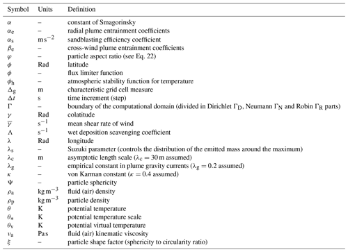
In continuum mechanics, the general form describing the passive transport of a substance mixed within a fluid (air) in a domain Ω derives from mass conservation which, in conservative flux form and using the Eulerian specification, reads (see Tables 1 and 2 for list of symbols)
where F=c u is the advective flux, G=c us is the sedimentation flux, is the diffusive flux, and S and I are the source and sink terms, respectively. In the expressions above, t denotes time, c is concentration (in kg m−3), u is the fluid velocity vector (i.e. wind velocity), us is the terminal settling velocity of the substance, and 𝕂 is the diffusion tensor (in m2 s−1). Note that the definition of the diffusive flux H explicitly assumes Fick's first law of diffusion.
Boundary conditions are imposed at the Dirichlet ΓD (inflow), Neumann ΓN (outflow) and Robin ΓR (ground) parts of the boundary of the computational domain Γ (with and ) as
where is the concentration prescribed at inflow (typically ), n is the outwards unit normal vector, and D=cud is the ground deposition flux (ud is the ground deposition velocity). Note that when the deposition flux D coincides with the sedimentation flux G (i.e. when us=ud), the boundary condition at ground reduces to the standard free-flow condition imposed at ΓN.
Table 1List of Latin symbols. Bold and doubled-lined fonts indicate vector and tensor quantities, respectively.

Equation (1) is the so-called ADS equation and, in FALL3D-8.0, has been extended to handle other substances different from tephra. Note that the passive transport equation (Eq. 1) neglects inertial terms and, consequently, assumes a low (≤ 1) particle Stokes number. In a general sense, substances in FALL3D-8.0 are grouped in three broad categories: particles, aerosols and radionuclides. The category “particles” includes any inert substance characterised by a sedimentation velocity. In the context of FALL3D-8.0, the category “aerosol” refers to substances potentially non-inert (i.e. with chemical or phase changes mechanisms) and having a negligible sedimentation velocity. Finally, the category “radionuclides” refers to isotope particles subject to radioactive decay. Each of these categories admits, in turn, different subcategories or “species”, defined internally as structures of data that inherit the parent category properties (see Table 3). For example, particles can be subdivided into tephra or mineral dust; aerosol species can include H2O, SO2, etc.; and radionuclides can include several isotope species. Finally, each subcategory of species is tagged with an attribute name that is used for descriptive purposes only.
Depending on the species under consideration, the mass source S and sink I terms in Eq. (1) can be decomposed as
where the superscripts denote emission source terms (Se; see Sect. 3.2.3), wet deposition sinks (Iw; see Sect. 3.2.4), particle aggregation source and sinks (Sa and Ia, respectively; see Sect. 3.2.6), radioactive decay source and sinks (Sr and Ir, respectively; see Sect. 3.2.7), and chemical reactions' source and sinks (Sc and Ic). Note that FALL3D-8.0 does not account for aerosol chemistry yet. However, the code has been designed to allow incorporating this functionality in future versions in a straightforward manner.
Table 3Types of categories and related subcategories of species in FALL3D-8.0.
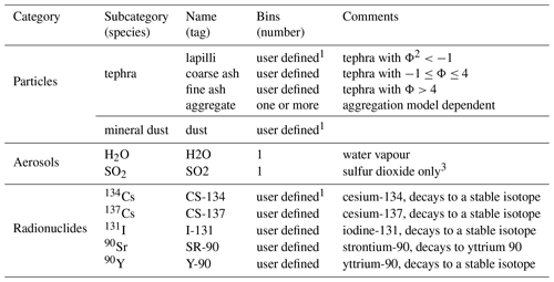
1 For any species in the category particles or radionuclides, users can specify the number of effective bins from a grain size distribution. 2 For tephra, the Φ number is defined as , where d is the particle diameter in millimetres. 3 SO2 chemistry not included yet in v8.0.
Table 4Parameterisations available in FALL3D-8.0 depending on each category and related subcategory (species). Note that, except for radioactive decay, all physical phenomena were already included in v7.x. However, several parameterisations have been updated to account for more recent developments.
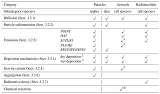
1 Only for volcanic aerosols. 2 Applies only to particles/aerosols smaller than 100 µm. 3 Cut-off at 100 and 1 µm assumed for below- and in-cloud scavenging, respectively. 4 Not included yet in v8.0.
When the ADS equation (Eq. 1) is discretised, species in the mixture are binned in nb discrete “classes” or bins, so that the total concentration c at any point of the domain decomposes as the sum of bin concentrations, i.e. . Substitution of bin discretisation in Eq. (1) yields to nb equations (one per discrete bin), each formally identical to Eq. (1):
Note that the nb equations for bins can be coupled by means of the source and sink terms, which define the eventual transfer of mass among different bins, e.g. in the case of particle aggregation/disegregation, chemical reactions and formation of child radionuclides.
3.2 Model parameterisations
Parameterisations in FALL3D have been revised and updated, removing deprecated options and adding new options available from more recent studies. Table 4 shows the parameterisations implemented in FALL3D-8.0 that are described in the following subsections.
3.2.1 Diffusion tensor
The atmospheric flow is characterised by large horizontal-to-vertical aspect ratios of wind velocities and length scales, as well as by an anisotropic momentum diffusion with the horizontal diffusion coefficient being typically much larger than the vertical one (e.g. Schaefer-Rolffs and Becker, 2013). For this reason, model diffusion that accounts for subgrid-scale atmospheric eddies is typically assumed anisotropic, with two distinct eddy diffusion coefficients along the horizontal and vertical dimensions:
In the case of FALL3D-8.0, the horizontal coefficient kh can be either assumed constant or parameterised as in Byun and Schere (2006):
where
In the equations above, Δg is a characteristic grid cell measure (e.g. the equivalent area length), α≅0.28 denotes the Smagorinsky constant, SΓ and SΛ are the stretching and shear strength (i.e. the two components of the bi-dimensional wind deformation), and kref is a reference horizontal diffusion for a reference grid cell size Δref (FALL3D-8.0 considers kref=8000 m2 s−1 for Δref=4 km). Equation (6) was proposed by Byun and Schere (2006) to overcome the dependency of horizontal diffusion on grid resolution and combines a Smagorinsky subgrid-scale (SGS) model giving the diffusion by transport (kht) with a formula that counteracts numerical over-diffusion in coarse discretisations (khn) so that the smaller one between kht and khn dominates. In this way, the effect of the transportive diffusion is minimised for coarse grids, whereas for fine discretisations the numerical diffusion term is reduced.
The vertical diffusion coefficient kv can also be either assumed constant or parameterised according to the similarity theory and distinguishing among surface layer, atmospheric boundary layer (ABL) and free atmosphere (e.g. Neale et al., 2010):
where κ is the von Karman constant (κ=0.4), z is the distance from the ground, u* is wind friction velocity, ϕh is the atmospheric stability function for temperature, hp is the ABL height, lc is a characteristic length scale, uh is the horizontal wind velocity modulus, and Fc is a stability function which depends on the Richardson number Ri. For lc and Fc, FALL3D-8.0 adopts the relationships used by the Community Atmosphere Model (CAM) 4.0 model (Neale et al., 2010):
where λc is the so-called asymptotic length scale (λc≈30 m). The atmospheric stability function for temperature ϕh is calculated as
where βh=5, γh=15, and L is the Monin–Obukhov length, defined as
with g denoting gravity, the mean potential virtual temperature and θ* the potential temperature scale. The parameters in Eq. (13) (i.e. L or ) are ideally furnished by the driving meteorological model. If not, and alternatively, FALL3D-8.0 estimates the friction velocity u* and the potential temperature scale θ* from the potential virtual temperature θv and the Richardson bulk number Rib as (Louis, 1979; Jacobson, 1999)
where zr and zo denote the reference and the ground roughness heights, and denotes the average between the two vertical levels. Given Rib, one can estimate u* and θ* as
where Prt is the turbulent Prandtl number (Prt≈1) and the stability functions Gm and Gh are given by (Louis, 1979; Jacobson, 1999)
3.2.2 Sedimentation velocity
Particle bins in the model are assumed to settle down with a sedimentation velocity equal to its terminal velocity:
where ρa and ρp denote air and particle density, d is the particle equivalent diameter, and Cd is the drag coefficient that depends on the Reynolds number, ( being the kinematic viscosity of air and μa its dynamic viscosity). For irregular particles, the drag coefficient Cd has to be obtained from experimental measurements. FALL3D-8.0 includes several parameterisations derived from laboratory results using natural and synthetic particles and that cover a wide range of particle sizes and shapes (characterised by sphericity, by circularity, or by some other model shape factor). Model options for the drag coefficient Cd include the following:
-
The GANSER model (Ganser, 1993) shows that
where and are two shape factors, dn is the average between the minimum and the maximum axis, and Ψ is the particle sphericity (Ψ=1 for spheres). For calculating the sphericity, it is practical to use the concepts of “operational” and “working sphericity”, Ψwork introduced by Wadell (1933) and Aschenbrenner (1956), which are based on the determination of the volume and of the three dimensions of a particle, respectively:
with , , where d1 is the longest particle dimension, d2 is the longest dimension perpendicular to d1, and d3 is the dimension perpendicular to both d1 and d2.
-
The PFEIFFER model (Pfeiffer et al., 2005), based on the interpolation of previous relationships by Walker et al. (1971) and Wilson and Huang (1979), shows
where is the particle aspect ratio ( denote the particle semi-axes).
-
The DIOGUARDI model (Dioguardi et al., 2018) demonstrates that
where ξ is a particle shape factor (sphericity to circularity ratio), for which Dioguardi et al. (2018) suggested an empirical correlation with sphericity Ψ as ξ=0.83Ψ.
Note that, in any case, the terminal velocity ws is defined by a triplet . As a result, particles with similar values of the three parameters can be grouped within the same model bin.
3.2.3 Emissions
The emission source term for the ith bin ( term in the bin equations; see Eq. 4) gives the mass per unit of time and volume (units of ) released at each point (cell) of the computational domain. FALL3D-8.0 can generate and handle multiple types of emission sources, internally defined as a data structure made of np discrete points, each “tagged” with a time-varying position and bin emission rate (source strength) Mip (in kg s−1). As a result, in a model grid cell results from summing emissions from all point sources laying within the cell volume V:
The total source strength Mo results from summing over all source points and bins, i.e.
Table 5Options available in FALL3D-8.0 for vertical distribution of mass and total source strength depending on the type of emission source Se.

Table 5 summarises the different (exclusive) options available in FALL3D-8.0 for the emission term and related source strength.
-
The POINT option assumes that all mass is emitted from a single point (np=1) located at height zt above ground level:
where fi is the ith bin mass fraction.
-
The HAT option defines a uniform vertical line of np source points spanning in height from zb (bottom) to zt (top) above the ground (i.e. with thickness zt−zb):
Note that this option includes as end-members the POINT option (if zb=zt) and a vertically uniform emission from ground to top (if zb=0).
-
The SUZUKI option (Suzuki, 1983; Pfeiffer et al., 2005) assumes a mushroom-like vertical distribution of np emission points depending on two dimensionless parameters (As and λs):
The Suzuki parameter As controls the vertical location of the maximum of the emission profile, whereas the parameter λs controls the distribution of the emitted mass around the maximum. When any of the previous source options are defined for volcanic plumes, it is useful to prescribe the total source strength (eruption mass flow rate) Mo in terms of the eruption column height H because this parameter is easier to be obtained from direct observations. To this purpose, FALL3D-8.0 includes two relationships that correlate Mo with H based on empirical observations and on 1-D plume model simulations, respectively. The first and simplest case considers the fit proposed by Mastin et al. (2009):
where a=140.8 is a constant and H is the eruption column height expressed in kilometres above the eruptive vent. Alternatively, the 1-D model fit by Woodhouse et al. (2016) can also be used to provide Mo depending on the surrounding atmospheric conditions:
where N is the Brunt–Väisälä frequency, co is a constant, and f is a function of the parameter given by
with the coefficients , , and , with αe and βe the radial and cross-wind plume entrainment coefficients (Costa et al., 2016b) and the mean shear rate of wind. The constant co in Eq. (30) depends on the conditions at the vent:
with Cs, Cv and Ca the specific heat capacities at constant pressure of the solid pyroclasts, gas phase and air, respectively, Ta and To the air and vent magma mixture temperatures, and n0 the gas mass fraction.
-
The PLUME option, valid only for volcanic plumes, uses the FPLUME-1.0 model (Folch et al., 2016) embedded in FALL3D-8.0. FPLUME-1.0 is a steady-state 1-D cross-section-averaged eruption column model based on the buoyant plume theory (BPT). The model accounts for plume bending by wind, entrainment of ambient moisture, effects of water phase changes, particle fallout and re-entrainment, and a model for wet aggregation of ash particles in the presence of liquid water or ice. As opposed to the previous cases, the PLUME source option automatically determines a bin-dependent vertical distribution of mass and computes height from Mo, or vice versa by solving an inverse problem.
-
The RESUSPENSION option considers the remobilisation and resuspension by wind of soil particles (e.g. mineral dust or volcanic ash previously deposited on the ground). Up to three different emission schemes are available in FALL3D-8.0 to obtain the vertical flux of suspended particles, from which Mo is obtained by multiplying by the associated surface cell area (see Folch et al., 2014, for details). Typically, the emission schemes for mineral dust are formulated in terms of the friction velocity. For example, emission scheme 1 (Westphal et al., 1987) considers
where FV is the vertical flux (in ), occurring only above a (constant) threshold friction velocity u*t (u* given in m s−1). An important limitation of Eq. (33) is that the vertical flux does not depend on either particle size or soil moisture. However, despite its simplicity, this parameterisation can be useful when information on soil characteristics (e.g. particle sizes and densities, moisture, roughness) is unavailable or poorly constrained. Emission scheme 2 (Marticorena and Bergametti, 1995; Marticorena et al., 1997) considers
where the experimental coefficient Sc (in cm−1) depends on the amount of available fine particles in the soil, and the threshold friction velocity is given by
with and (the lower bound of the fit corresponds to particles of ≈ 10 µm in size). Note that in Eq. (35), ρp and ρa are particle and air densities (expressed in g cm−3), g is gravity (in cm s−2), d is the particle size (in centimetres), Re is the Reynolds number parameterised as a function of the particle size, and u*t is given in cm s−1.
Finally, emission scheme 3 (Shao et al., 1993; Shao and Leslie, 1997; Shao and Lu, 2000) considers that the uplift from surface of the fine fraction of soil particles is controlled by the bombardment of saltating particles of larger sizes (≥ 63 µm), which breaks the cohesive forces of smaller particles.
Based on theoretical and experimental results, Shao et al. (1993) found an expression for the vertical flux of dust particles of size d ejected by the impact of saltating particles of size ds:
where αs (in m s−2) is the coefficient of sandblasting efficiency determined experimentally (Shao and Leslie, 1997) and FH is the horizontal flux (in ) of saltating particles:
where co is an empirical dimensionless constant close to 1. In this scheme, the threshold friction velocity u*t(d) is given by
where γ is an experimental parameter ranging between and kg s2 (a value of kg s2 is assumed in FALL3D-8.0).
3.2.4 Deposition mechanisms
In FALL3D-8.0, dry and wet deposition mechanisms can be activated for any type of bin below a certain particle/aerosol size.
Dry deposition on the ground is imposed prescribing the deposition velocity through a Robin boundary condition in Eq. (2). FALL3D-8.0 admits two dry deposition parameterisations which describe the vertical depositional fluxes by Brownian diffusion and inertial impaction, parameterised through the Schmidt and the Stokes numbers, respectively. The first option considers the mass-consistent formulation proposed by Venkatram and Pleim (1999):
where ra describes the effects of aerodynamic resistance and rb the quasi-laminar resistance (e.g. Brandt et al., 2002, and references therein). The aerodynamic resistance ra can be calculated as
with zo denoting the ground roughness height and ϕh the atmospheric stability function for temperature given by Eq. (12). The quasi-laminar resistance rb can be expressed in terms of the Schmidt number and Stokes number (with ν kinematic viscosity of air and D molecular diffusivity of particles) (e.g. Brandt et al., 2002):
The second option is that proposed by Feng (2008), which essentially differs from Eq. (39) in the estimation of rb:
where c1=0.0226, c2=40300 and c3=15330 are dimensionless parameterisation constants, Re* is the Reynolds number (computed with the friction velocity u*), and a and b are coefficients that depend on the particle size and surface characteristics. Note that Feng (2008) gives a and b best-fit values for seven land use categories and four aerosol size modes: nuclei (up to 0.1 µm), accumulation (up to 2.5 µm), coarse (up to 10 µm) and giant (up to 100 µm). A cut-off is assumed above this size because the sedimentation velocity term ws dominates, and therefore the dry deposition contribution can be neglected.
Wet deposition mechanisms in FALL3D-8.0 are assumed to occur only within the ABL, and the corresponding sink term in Eq. (3) is parameterised as
where Λ differs for in-cloud (ic) and below-cloud (bc) sinks. For below-cloud scavenging (precipitation), Λbc is estimated from the total precipitation rate as (e.g. Brandt et al., 2002; Jung and Shao, 2006)
where P is the precipitation rate (in mm h−1), and and b=0.79 are two empirical constants. For in-cloud scavenging (rainout), the model considers a parameterisation based on the atmospheric relative humidity (RH; in %) as in Brandt et al. (2002):
with , RHt=80 % (threshold value) and RHs=100 % (saturation value). Two critical particle cut-off sizes of 100 and 1 µm are assumed for below- and in-cloud scavenging, respectively.
3.2.5 Gravity spreading of the umbrella region
Large explosive volcanic eruptions can generate gravity-driven transport mechanisms that dominate over passive transport close to the vent and cause a radial spreading of the cloud (e.g. Woods and Kienle, 1994; Sparks et al., 1997). In order to simulate this mechanism, FALL3D-8.0 includes a gravity current model (see Costa et al., 2013, and the erratum published in June 2019). This option consists on adding a radial velocity field to the background wind, so that contributions from both passive and density-driven mechanisms are accounted for. The added radial wind is centred above the eruptive vent in the umbrella region and extended up to a radius R given by
where t is time since eruption onset, λg is an empirical constant constrained to ≈0.2 from direct numerical simulations (Suzuki and Koyaguchi, 2009), N is the Brunt–Väisälä frequency, and q is the volumetric flow rate into the umbrella region, estimated as (Morton et al., 1956; Suzuki and Koyaguchi, 2009; Costa et al., 2013, as correct in the erratum published in 2019)
where Mo is the total source strength (i.e. mass eruption rate), ke is the air entrainment coefficient, and c is a constant that from varies from tropical to midlatitude/polar locations:
Given the radius R, the radial velocity field as a function of distance r is calculated as (Costa et al., 2013)
where ur(R) is the front velocity:
In order to avoid sudden jumps at the gravity current front, FALL3D-8.0 interpolates the front velocity ur(R) with far field wind velocity using an exponential decay function of the cloud thickness hc as
where r is the distance from the current front.
3.2.6 Aggregation
Aggregation of tephra particles can occur inside the eruptive columns or even downwind in ash clouds during atmospheric dispersion, thereby affecting the sedimentation dynamics and deposition of volcanic ash. FALL3D-8.0 includes some simple a priori aggregation options and a wet aggregation model (Costa et al., 2010; Folch et al., 2010) that can be activated for tephra bins. The a priori options consist of user-defined or empirically based predefined fractions of aggregating classes being transferred to one or more class of aggregates at the source points (i.e. aggregation is performed before transport). In contrast, in the wet aggregation model, ash particles aggregate on a single effective class of diameter dA; i.e. aggregation only affects tephra bins with diameter smaller than dA, typically in the range 100–300 µm. This option can run embedded in FPLUME-1.0 or as a stand-alone module. Consider a tephra grain size distribution in which k particle bins can aggregate. Then, the aggregation model defines the source (Sa) and sink (Ia) bin terms for the corresponding k+1 bins as
where dj(<dA) and ρj are, respectively, the diameter and density of particles in bin j, and is the number of particles per unit volume and time that aggregate. The model assumes that this is proportional to the total particle decay per unit volume and time , i.e.
where
is the number of primary particles of diameter dj in an aggregate of diameter dA, kf is a fractal pre-factor (kf≈1), and Df is the fractal exponent (Df≤3). The model estimates the total particle decay per unit time integrating the coagulation kernel over all particle sizes, depending on the sticking efficiency times a collision frequency function which accounts for Brownian motion, collision due to turbulence as a result of inertial effects, laminar and turbulent fluid shear, and differential sedimentation (see Costa et al., 2010; Folch et al., 2016, for details).
3.2.7 Radioactive decay
FALL3D-8.0 can handle the fate of radioactive material dispersed from accidental releases (e.g. Brandt et al., 2002; Leelössya et al., 2018). Five common species of radionuclides have been implemented: cesium (134Cs, 137Cs) and iodine (131I), which decay to stable isotopes, and 90Sr, which decays to the unstable isotope 90Y (see Table 6).
Radionuclide species need to specify the source () and the sink () terms in Eq. (3) associated with the radioactive production or decay of the isotope n, respectively. The radioactive decay term indicates the mass per unit volume of the isotopes of type n that decays per unit time:
where cn is concentration (expressed in kg m−3) and kr a constant specific of each isotope (decay rate) that can be calculated from the radioactive element half life t1∕2 as . Values of t1∕2 and kr for common radionuclides are reported in Table 6. Note that the decay term is more relevant for isotopes with short half lives, e.g. for 131I, which has d (Brandt et al., 2002; Leelössya et al., 2018).
The radioactive decay term of the isotope n constitutes a sink for the isotope itself. However, the decay of the isotope m, father of isotope n, constitutes a source for the isotope n:
where pmn is the relative probability of decay of the isotope m to the isotope n. If the isotope m has only one child n, the relative probability of the branch m↦n is pmn=1. Note from Table 6 that 134Cs, 137Cs and 131I decay to stable isotopes, whereas 90Sr decays to 90Y which, in turn, is unstable and decays to the stable isotope 90Zr. The production rate of 90Y is therefore equivalent to the decay rate of 90Sr.
In FALL3D-8.0, the radioactive decay is implemented by firstly transporting the radionuclides for a time step Δt and then by evaluating the decay during the same time step. For radionuclides that decay to a stable isotope (134Cs, 137Cs and 131I), it is considered that after a time step Δt the concentration decreases as
whereas for decay to an unstable isotope (yttrium), the concentration varies as
where cY and cSr are, respectively, the concentrations of 90Y and 90Sr, and kY and kSr are the corresponding decay rates.
3.3 Data insertion
Instrumentation aboard the new generation of geostationary satellites provides an unprecedented level of spatial resolution and temporal frequency (2 to 4 km pixel size and 10 to 15 min observation period; see Table 7), yielding a quasi-global coverage considering the overlap of different existing platforms. This is very suitable for high-resolution model data assimilation and related uncertainty quantification, as well as to implement ensemble-based dispersal forecast systems. These aspects are still under development and hopefully will be part of next FALL3D model distributions. However, FALL3D-8.0 already includes the possibility of initialising a model run from satellite retrievals. This option, known as data insertion, is typically used in dispersal of volcanic ash and aerosols (mainly SO2) in order to reduce model uncertainties coming from the eruption source term.
Satellite retrievals giving cloud column mass of fine volcanic ash and aerosols can be furnished to the model together with values of cloud thickness, with the latter needed in order to compute initial concentration (in kg m−3) from column mass (in kg m−2). In the model initialisation step, gridded satellite data are interpolated into the model grid imposing conservation of mass when concentration values are computed for each model grid cell, i.e. ensuring that the resulting column mass in the model (computed concentration multiplied by cloud thickness) equals that of satellite data over the same cell area. Examples showing how data insertion improves model accuracy are given in the companion paper (Prata et al., 2020).
4.1 Coordinate mappings and scaling
Consider the ADS equation (Eq. 1) written in a Cartesian system of coordinates assuming a diffusion tensor as in Eq. (5) and a sedimentation velocity aligned with the vertical coordinate z:
It is straightforward to discretise the above equation in a “brick-like” computational domain Ωc using a structured regular (i.e. equally spaced) mesh, although the regularity condition is typically relaxed across the vertical direction so that the vertical grid resolution increases close to ground, where higher gradients are expected. In order to use other coordinate systems, Eq. (59) can be written on a generalised orthogonal system of coordinates (e.g. Toon et al., 1988; Byun and Schere, 2005):
where C is the scaled concentration, are the scaled wind components, are the scaled diffusion coefficients, and S* and I* are the scaled source and sink terms. The implementation of a generalised equation like Eq. (60) presents two major advantages. On one hand, the generalised equation reads formally equal to that in Cartesian coordinates, so that little computational penalty exists to map physical domains (e.g. accounting for Earth's curvature and topography) to a “brick-like” computational domain (see Fig. 1) by using coordinate-dependent horizontal and vertical mappings. On the other hand, a generalised form simplifies the structure and implementation of the code because the model can be solved on various horizontal (Cartesian, spherical, Mercator, polar stereographic, etc.) and vertical (terrain-following, σ-coordinate, etc.) coordinate systems using only one solving routine. To this purpose, one needs first to scale the model coordinates and some terms in the equation using adequate mapping and scaling factors, then solve for the scaled concentration C in the regular computational domain Ωc (as in Cartesian coordinates) and, finally, transform the scaled concentration back to the original one.
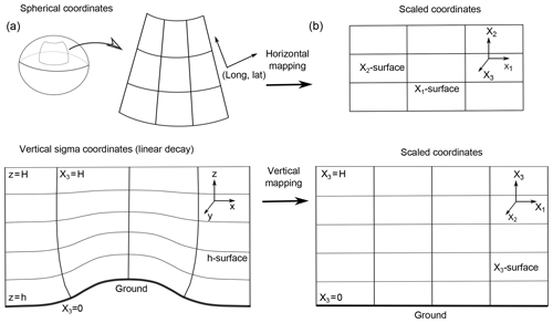
Figure 1Mapping of coordinates from the physical domain (a) to a brick-like computational domain (b) along the horizontal and vertical dimensions. Horizontal mapping corrects for Earth's curvature; vertical mapping accounts for topography.
In general and given two orthogonal coordinate systems, and , coordinate mapping factors are given by the terms mij of the Jacobian transformation matrix 𝕄:
but, for the transformations considered here, 𝕄 will always be diagonal with three non-zero components (m1, m2 and m3). For example, in the horizontal transformation to spherical Earth surface coordinates (λ,ϕ), one has
where Re is the radius of the Earth, and λ, ϕ and γ are the longitude, latitude and colatitude, respectively (in Rad). Trivially, this transformation yields to m1=sin γ and m2=1. Table 8 gives horizontal mapping factors for different coordinate systems (Toon et al., 1988). In most practical cases, FALL3D-8.0 simulations only consider spherical coordinates, but other options are in principle possible. For vertical transformations, FALL3D-8.0 incorporates a new σ-coordinate system with linear decay (Gal-Chen and Somerville, 1975) in which
where h(x,y) is the terrain height and HT the height of the top of the computational domain. In the σ-coordinate system, the influence of the terrain decreases linearly with height, from terrain-following at the surface (X3=0) to a rigid lid at the top of the computational domain (X3=HT). This option has been added to partially correct numerical oscillations in the previous terrain-following model mapping (), which can appear near the surface in the case of flows over mountain ranges and propagate upwards (Schar et al., 2002).
Table 8Horizontal mapping factors for different coordinate systems where λ is longitude, ϕ latitude, R the radius of the Earth, γ the colatitude, and ϕo the latitude at which the projection is true. Mercator and polar stereographic projections use Cartesian coordinates projected into the Earth's surface, i.e. account for curvature. Regular Cartesian coordinates should be used only for local domains, where the Earth's curvature can be neglected.

Table 9Vertical mapping factors z←X3 for different coordinate systems, where h(x,y) is topography and H is the top of the computational domain.
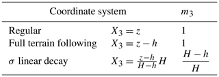
Table 10Scaling factors for the different terms in the generalised coordinate ADS equation (Eq. 60).
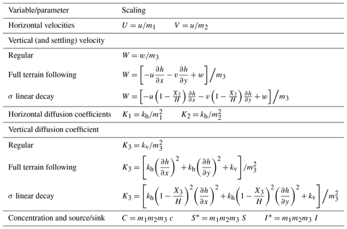
Table 9 gives the vertical mapping factors for the different coordinate systems available in FALL3D-8.0. Once defined, these coordinate mapping factors are used to scale the variables and parameters that appear in the generalised equation (Eq. 60). The scaling of scalar quantities is straightforward since it only involves the Jacobian determinant of the transformation, e.g. for concentration and so on. Note that for a volume one has dV=m1m2m3dv, so that the mass comprised in a cell dX1dX2dX3 of the computational domain is equal to that in the transformed cell of the physical domain. The horizontal velocity components are trivially scaled as
whereas for the vertical component one has to consider that, in terrain-following coordinate systems, the coordinate X3 depends also on (x,y) through the terrain elevation h(x,y):
Basic algebra manipulation yields to the scaling factors shown in Table 10 for the different vertical coordinate systems. Note that the expression above implicitly contains the correction for topography in the vertical velocity. Finally, scaling factors for diffusion coefficients can also be obtained after some manipulation (Toon et al., 1988; Byun and Schere, 2006).
4.2 Discretisation and solving algorithm
FALL3D solves for each model bin the 3-D generalised equation (Eq. 60) using a fractional step method, which splits the equation along each spatial direction (Folch et al., 2009):
with the solving order of each resulting one-dimensional ADS equation being permuted in each successive time step in order to avoid any privileged direction. One advantage of this splitting strategy is that, even if each one-dimensional equation is solved explicitly in time, the result is a semi-implicit scheme that adds stability.
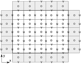
Figure 2Arakawa D grid on a 2-D computational domain limited by the bold line. Scalar quantities are stored/computed at the centre of the cells (empty circles), whereas the u and v velocity components are staggered at its respective cell faces. One row of ghost cells is shown in grey for reference; the actual number of ghost cells needed depends on the numerical stencil (order of the solving algorithm). The 3-D grid is formed as a succession of 2-D layers, with the w velocity components at the bottom/top faces of the cell.
In FALL3D-8.0, the “brick-like” computational domain is discretised using a variation of the staggered Arakawa D grid, in which the wind velocity components are evaluated at the respective cell faces and the rest of scalar quantities at the cell centres (Fig. 2). Note that this configuration is very convenient for solving the 3-D equation in a fractional manner because, when solving each one-dimensional case, wind velocities are already aligned with the boundaries of the corresponding one-dimensional cells. The previous versions of FALL3D used the classical LW central-difference scheme for solving the resulting one-dimensional ADS equations in Eq. (67), combined with a slope limiter to reduce numerical over-/undershooting near discontinuities. This resulted in a second-order accuracy except near sharp concentration gradients where, nonetheless, accuracy remained higher than in a first-order upwind method. The main advantage of using the LW scheme was its simplicity but, in contrast, it is well known that it introduces numerical dissipation that prevents accurate resolution of discontinuities, leading to over-diffusive results. In order to circumvent this drawback, FALL3D-8.0 uses instead a high-resolution Kurganov–Tadmor (KT) scheme that can be combined either with a fourth-order explicit Runge–Kutta or with a first-order Euler time-marching method. The latter option, even if less accurate, is still supported for computational efficiency reasons because it implies 4 times less solver calculations.
Consider the general one-dimensional advection-diffusion equation for a scalar variable c(x,t) on its conservative form:
where, in our particular case, F=c u is the advective flux and is the diffusive flux (as already introduced, u(x,t) and k(x,t) are the velocity and diffusivity, respectively). Consider also a 1-D computational domain discretised as in Fig. 2, where c is computed at cell centres (“mass” points) and u is stored at staggered cell boundaries, which do not need to be equally spaced. The semi-discrete form of the KT scheme can be written at centre of each cell i in terms of fluxes at boundaries as (Kurganov and Tadmor, 2000):
where is the ith cell width and
Note that, in the expression above, the last equality holds because our flux G depends only on the gradient of c, i.e. . In Eq. (70), is the maximum absolute value of the eigenvalue of the Jacobian matrix of F (in our particular case, it reduces to ), and cr and cl are, respectively, right and left values at a cell boundary, computed as
where
and ϕ(r) is a flux limiter function (e.g. Sweby, 1984). Options available in FALL3D-8.0 are the well-known superbee ϕs(r) and minmod ϕm(r) (Roe, 1986):
Note that c is needed at two extra mass points in order to evaluate and at the left/right cell boundaries, respectively. In other words, the “stencil” of the KT scheme needs two ghost nodes at the boundaries of the computational domain or a two-point halo for internal domains in the case of parallel domain decomposition. Note also that the solving strategy derives from a one-dimensional finite-volume formulation that, in our one-dimensional case, is also in practice equivalent to using linear finite elements.
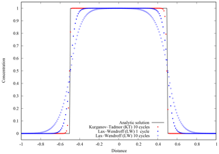
Figure 3Benchmark 1 results. Step-like discontinuity given by Eq. (80) moving right at constant velocity u=1 and without diffusion k=0 on a domain with periodic boundary conditions. The solid black line shows the analytic solution after each periodic cycle, which coincides with the initial condition (t=0). Red dots show the KT + RK4 numerical solution after simulating 10 cycles (at t=20). Blue dots and blue circles show the LW + EU1 results after 1 cycle (t=2) and 10 cycles (t=20), respectively. Note that mass (area below curves) is conserved in all the cases, but the KT + RK4 scheme adds almost no numerical diffusion and preserves discontinuities. Results use 200 equally spaced grid cells.
Time marching from tn to in Eq. (69) can be performed with the explicit first-order-in-time Euler method (EU1):
or, alternatively, using the classical fourth-order Runge–Kutta method (RK4), in which
with
where the function f(t,c) is given on the right-hand side of Eq. (69). In any case, the Courant–Friedrichs–Lewy (CFL) condition can be imposed to guarantee convergence in time integration (e.g. Hindmarsh et al., 1984) along each one-dimensional problem:
multiplied by a user-defined safety factor. This factor should theoretically be lower than 1 in fully explicit cases but, given the semi-implicit nature of the splitting algorithm, slightly larger values can also yield to stability.
4.3 Algorithm benchmarks
Three benchmark cases serve us to illustrate the gains of the KT + RK4 numerical scheme with respect the former LW + EU1 implemented in the previous versions of the code.
Example 1 considers the pure advection (k=0) of a step-like discontinuity. Consider a 1-D domain with an initial concentration of
that is advected by a uniform velocity field u=1. Periodic conditions are imposed at the boundaries, so that “mass” leaving the computational domain at x=1 is re-injected at . As a result, the initial condition is periodically recovered after each cycle with a period t=2. Results are shown in Fig. 3. Note how, as opposed to LW, the KT scheme adds almost no numerical diffusion and preserves discontinuities. In addition, because of its higher order in time, the KT + RK4 scheme preserves the solution, whereas for LW + EU1 accuracy deteriorates with time (compare the accuracy of the LW + EU1 solutions after 1 and 10 cycles in Fig. 3).
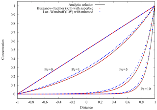
Figure 4Benchmark 2 results. Steady-state solutions for different Péclet numbers (Pe) on a domain with boundary conditions c=0 at and c=1 at x=1. Black lines show the respective analytic solutions given by Eq. (81). Red and blue dots show, respectively, the KT + RK4 and LW + EU1 numerical solutions. The case of Pe=0 (pure diffusion problem) has a linear solution and is exactly matched by both schemes. For the rest of the cases, KT + RK4 outperforms LW + EU1. Results use 200 equally spaced grid cells.
Example 2 considers the classical 1-D advection–diffusion problem for the onset of numerical instability in a domain subject to the boundary conditions c=0 at and c=1 at x=1. The problem has a steady-state analytic solution given by
where is the Péclet number. Figure 4 shows the steady-state solutions for different Péclet numbers, illustrating also how KT + RK4 outperforms LW + EU1 as the Péclet number increases.
Example 3 considers a case with pure advection (k=0) on a 2-D domain with an initial condition at t=0 given by a conic concentration distribution with a unit (c=1) peak concentration centred at and having a radius r=0.1 (Fig. 5a). The cone is advected by a rotating clock-wise velocity field centred at (0,0):
with an angular velocity Ω=π (in Rad s−1), so that each cycle is repeated with a period of t=2. Concentration profiles along two transects A (y=yc) and B (x=0) after two cycles (i.e. at t=4) are shown in Fig. 5b and c, respectively. Note again the substantial improvement in the KT + RK4 scheme, which performs well even in this numerically challenging test.
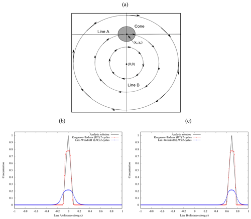
Figure 5Benchmark 3 results. (a) A cone centred at with radius r=0.1 (shaded circle) is advected by a rotating velocity field with angular velocity Ω=π in a computational domain . Plots in panels (b) and (c) show concentration profiles after two cycles along lines A (y=yc) and B (x=0). The solid black line shows the analytic solution after each cycle. Red and blue dots show the KT + RK4 and LW + EU1 numerical solutions, respectively. Results use 200 equally spaced cells along each direction.
Table 11Summary of the FALL3D-8.0 model tasks.

1 Model input file (same for all tasks). 2 Number of processors along each spatial dimension in domain decomposition. If not given, the execution is serial.
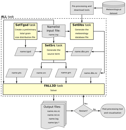
In FALL3D-8.0, the pre-process auxiliary programmes have been parallelised and embedded in the code, so that a single executable file exists for all the pre-process steps and execution workflow (see Fig. 6). These formerly independent programmes can still be run individually as model tasks (specified by a programme call argument) or, alternatively, concatenated with the model in a single execution. In the first case, pre-process tasks generate output files that are later given as inputs to the model task. This is similar to what occurred in the previous version (v7.x) but with the difference of a parallel pre-process. In contrast, the second option does not require intermediate file writing/reading and therefore saves disk space and overall computing time. In any case, all tasks share a unique model input file and generate their own log file to track execution and report eventual warnings and errors. Possible task options are summarised in Table 11 and include the following:
-
Task SetTgsd can generate Gaussian and bi-Gaussian particle grain size distributions in Φ (log-normal in diameter) or, alternatively, Weibull and bi-Weibull distributions (Costa et al., 2016a), and assumes a linear variation of density and particle shape factor between two specified cut-offs. For other kinds of grain size distributions, the user must provide a total grain size distribution file (name.tgsd).
-
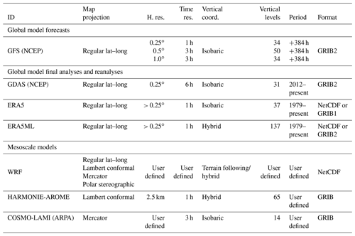
Task SetDbs interpolates all the required meteorological data from the original grid of the driving meteorological models to the computational domain. Table 12 summarises the different meteorological drivers available in FALL3D-8.0. Global datasets include ERA5, the new reanalysis from the European Centre for Medium-Range Weather Forecasts (ECMWF) (Hersbach and Dee, 2016), the National Centers for Environmental Prediction (NCEP) Global Forecast System (GFS) and Global Data Assimilation System (GDAS) final analysis. Regional models supported include the Advanced Research Weather Research and Forecasting (WRF) (ARW) core of the WRF model (Skamarock et al., 2008), the mesoscale models HARMONIE-AROME (Bengtsson et al., 2017) and the COSMO-LAMI, run by the Italian Regional Environmental Protection Agency (ARPA). Note that some former dataset options have been deprecated in v8.x. The FALL3D-8.0 distribution package provides a set of utilities to download and pre-process meteorological data for the SetDbs model task. Python scripts are provided to download and crop the variables required by the model. ERA5 can be obtained on either model levels (137 vertical levels) or pressure levels (37 vertical levels) via the Climate Data Store (CDS) infrastructure. GFS datasets can be accessed using the online archive of real-time weather model output from the National Operational Model Archive and Distribution System (NOMADS) (Rutledge et al., 2006). The NCEP FNL (final) operational global analysis and forecast data from the Global Data Assimilation System (GDAS) can be accessed using the Open-source Project for a Network Data Access Protocol (OPeNDAP) through the Thematic Real-time Environmental Distributed Data Services (THREDDS) Data Server (TDS) offered by the National Center for Atmospheric Research (NCAR) Research Data Archive (RDA).
-
Task SetSrc generates different emission source terms (see Sect. 3.2.3 and Table 4), including the PLUME option based on the FPLUME-1.0 model (Folch et al., 2016). If necessary, it also performs a priori tephra particle aggregation (Sect. 3.2.6) and a TGSD cut-off in order to select the effective bins considered in the atmospheric transport.
-
Task FALL3D runs the FALL3D-8.0 model itself.
-
Task All runs all previous tasks consecutively as a single parallel execution.
Parallelisation in FALL3D-8.0 considers a 3-D domain decomposition, with freedom for user to choose the number of processors along each direction. In contrast, previous versions considered two different levels of parallelisation: one on particle bins and another on domain but only along the vertical dimension. Parallelisation on bins was convenient in v7.x because no interaction among bins existed, but such a form of trivial parallelism has been deprecated given that it would now yield to unnecessary communication penalties. Note also that the full 3-D domain decomposition allows solving on much larger grid sizes before reaching hardware memory limits.
In terms of runtime performance, it is important to recall that the splitting algorithm combined with the RK4 time marching implies solving a series of 1-D equations four times along each spatial dimension, contrasting with a single solution for the EU1 case. In other words, each time integration step of Eq. (67) using the RK4 scheme along X1 implies solving ny×nz one-dimensional problems four times, the solution along X2 implies solving nx×nz problems four times and so on. In order to minimise the number of communications between neighbouring processors, it is more convenient to compute first each of the four partial increments in Eq. (78) for all the 1-D problems on a given dimension. This optimises swapping communications among domain partitions because a single swapping request (i.e. one MPI send/receive call) communicates all the data necessary to compute the next RK4 increment for the whole mesh. In contrast, if all partial increments in Eq. (78) were computed for each 1-D problem, it would require as many swapping requests as 1-D problems involved. Clearly, this solving approach is convenient but it presents two drawbacks. Firstly, it obviously increases the amount of memory required and, secondly, it poses an issue on memory data access, with potential increase of cache memory misses given the more frequent access to data. Moreover, when one solves for the dimensions stored on array lowest axes, memory data access is scattered and therefore less efficient. This issue has been addressed in FALL3D-8.0 by rearranging the components of the velocity and diffusion arrays, with the dimension to solve being stored always in the fastest axis, and also by transposing the concentration array that has to be updated at the first partial increment. Such a memory management strategy allows exploiting always contiguous cache memory positions on any spatial dimension.
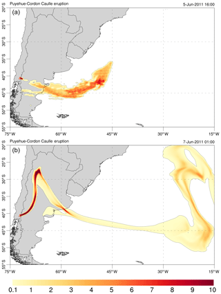
Figure 7Simulation results for the 2011 Cordón Caulle eruption. The model was configured as shown in Table 13 and solved on the grid cells used in Sect. 6 for the scalability analysis. (a) PM10 ash cloud column mass contours (in kg m−2) on 5 June 2011 at 16:00 UTC, just after satellite data insertion. (b) Same on 7 June 2011 at 01:00 UTC after model evolution assuming a constant column height of 10 km a.v.l.
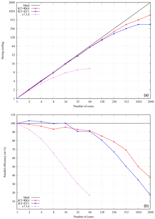
Figure 8Strong scaling results on MareNostrum 4 supercomputer for the Cordón Caulle simulation using a cell grid. (a) Scaling curves up to 2048 processors for the RK4 (red) and EU1 (blue) time integration schemes. Results using code v7.3.4 are also shown with up to 64 processors only (pink). Ideal strong scaling behaviour is indicated by the solid black line. Note that the scaling curves refer to the total computing time and therefore include I/O operations, not just computing time. (b) Parallel efficiency (Eq. 83) depending on the number of computation units.
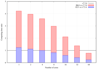
Figure 9Computing time ratio between code v7.3.4 and v8 depending on the number of processors. Results for EU1 (blue bars) and RK4 (red bars) including I/O operations.
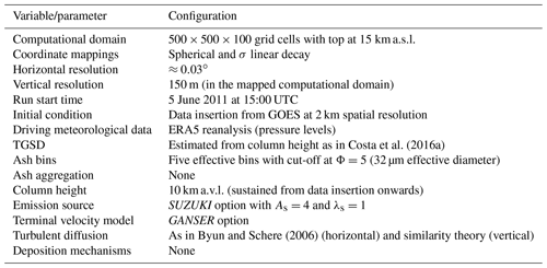
Table 13FALL3D-8.0 model configuration for the Cordón Caulle simulation example shown in Sect. 6.
All the aspects discussed above have improved substantially the performance and scalability of the code. As an example of strong scaling (i.e. time to solution for a fixed problem size), let us consider a real-case ash dispersal simulation from the 2011 Cordón Caulle eruption (e.g. Collini et al., 2013). The model was configured as shown in Table 13 and solved on a typical grid size of computational cells (horizontal model resolution of ). For illustrative purposes, Fig. 7 shows model snapshots of ash cloud column mass at two different times. Figure 8a shows strong scaling results (speedup) up to 2048 processors obtained on the MareNostrum 4 supercomputer, composed by general-purpose nodes with 48 Intel Xeon Platinum processors interconnected by a 100 GB Intel Omni-Path full-fat tree. For comparison, this figure shows also the strong scaling curve obtained with latest code (v7.3.4), in this case limited to 64 processors (larger values were not possible on this grid using v7.3.4 given the former one-dimensional domain decomposition along z). Figure 8b plots the corresponding parallel efficiencies, defined as
where t1 is the total computing time with one processing unit, and tN is the time with N processing units. Note that ideal strong scaling implies a parallel efficiency of 100 %. Clearly, v8.x improves notably the scalability of the code, with a trend close to that of perfect scaling up to ≈ 100 processors (parallel efficiency ≥ 90 %). Depending on the time integration scheme, values of parallel efficiency above 50 % are obtained with up to 512 and 1024 processors for EU1 and RK4, respectively. This is in striking contrast with v7.3.4, for which parallel efficiency already drops below 50 % with only 16 processors (Fig. 8b).
Much better v8.x code performance is also observed not only in terms of code scalability but also in terms of total computing time. Figure 9 shows the computing time ratio (total elapsed time) between v7.3.4 and v8 depending on the number of processors and the time integration scheme. The EU1 case (i.e. equal order of accuracy in time to that in v7.3.4), shows a similar serial performance, only with an insignificant computation overhead probably due to algorithmic differences. However, this overhead is rapidly balanced with only four processors, and v8.x with EU1 is already up to 4 times faster than v7.3.4 with 64 processors. The RK4 case (i.e. fourth order of accuracy in time) is around 4 times slower than v7.3.4 for the serial execution. This is a logical result given that the RK4 scheme needs to iterate 4 times more to solve in time. However, this penalty is also rapidly balanced as the number of processors increases, and RK4 already outperforms v7.3.4 in absolute terms with only a few tens of processors. In summary, v8.x clearly shows a much better scalability and performance (absolute computing time to solution for a given problem and computational resources) than v7.3.4. The companion paper (Prata et al., 2020) contains a detailed model validation and shows that this is also true in terms of model accuracy.
After 15+ years, the atmospheric transport model FALL3D has been completely rewritten and modernised to overcome legacy constraints in the former release (v7.x) that precluded the introduction of new functionalities and seriously limited the scalability and performance of the code on hundreds or thousands of processors. With this, FALL3D-8.0 can be considered as a baseline for the successive optimisations and preparation for exascale computing. However, as detailed in the paper, v8.x already contains remarkable improvements and updates on model physics, numerics and performance. In particular, the code has been prepared to deal also with particles different from tephra, aerosols and radionuclides, includes new coordinate mapping options, a more efficient and less diffusive solving algorithm (KT) that can be combined with a high-order-in-time solver (RK4) and a better memory management and parallelisation strategy based on a full 3-D domain decomposition. Strong scaling results have shown perfect scaling with a few hundred processors and a parallel efficiency above 50 % with 1024 processors. This remarkable improvement is also true in terms of performance (total computing time), with v8.x outperforming the previous release by a factor of 4 with only 64 processors. Further expected improvements in the preparation towards exascale include memory optimisation, introduction of thread parallelism (OpenMP), code vectorisation, porting to accelerators (GPUs), performance portability, load balance, asynchronous I/O and preparation for emerging heterogeneous architectures (exascale hardware prototypes).
FALL3D is available under version 3 of the GNU General Public License (GPL) at https://gitlab.com/fall3d-distribution (last access: 17 March 2020, Folch, 2020).
AF and LM have written the bulk of FALL3D-8.0, with contributions from NG and GM. AC revised and updated all physical parameterisations implemented in the code. NG and MH have performed optimisations and the performance and scalability analysis. AF and AC wrote the manuscript with the input of all coauthors.
The authors declare that they have no conflict of interest.
This work has been funded by the H2020 Centre of Excellence for Exascale in Solid Earth (ChEESE) under grant agreement no. 823844. AC and GM acknowledge the European project EUROVOLC (grant agreement no. 731070) and the Ministero dell'Istruzione, dell'Università e della ricerca (MIUR, Rome, Italy) Ash-RESILIENCE project (grant agreement no. 805 FOE 2015). The authors thank Andrew Prata (BSC) for providing satellite retrievals of ash column mass, and Fabio Dioguardi and an anonymous reviewer for their constructive comments.
This research has been supported by the Centre of Excellence for Exascale in Solid Earth (ChEESE) (grant no. 823844), the EUROVOLC (grant no. 731070) and the Ash-RESILIENCE (grant no. 805 FOE 2015).
This paper was edited by Augustin Colette and reviewed by Fabio Dioguardi and one anonymous referee.
Aschenbrenner, B. C.: A new method of expressing particle sphericity, J. Sediment. Petrol., 26, 15–31, 1956. a
Bear-Crozier, A., Kartadinata, N., Heriwaseso, A., and Møller Nielsen, O.: Development of python-FALL3D: a modified procedure for modelling volcanic ash dispersal in the Asia-Pacific region, Nat. Hazards, 64, 821–838, 2012. a
Bengtsson, L., Andrae, U., Aspelien, T., Batrak, Y., Calvo, J., de Rooy, W., Gleeson, E., Hansen-Sass, B., Homleid, M., Hortal, M., Ivarsson, K.-I., Lenderink, G., Niemela, S., Nielsen, K., Onvlee, J., Rontu, L., Samuelsson, P., Munoz, D., Subias, A., Tijm, S., Toll, V., Yang, X., and Koltzow, M.: The HARMONIE-AROME Model Configuration in the ALADIN-HIRLAM NWP System, Mon. Weather Rev., 145, 1919–1935, https://doi.org/10.1175/MWR-D-16-0417.1, 2017. a
Biass, S., Scaini, C., Bonadonna, C., Folch, A., Smith, K., and Höskuldsson, A.: A multi-scale risk assessment for tephra fallout and airborne concentration from multiple Icelandic volcanoes – Part 1: Hazard assessment, Nat. Hazards Earth Syst. Sci., 14, 2265–2287, https://doi.org/10.5194/nhess-14-2265-2014, 2014. a
Bonasia, R., Scaini, C., Capra, L., Nathenson, M., Siebe, C., Arana-Salinas, L., and Folch, A.: Long-range hazard assessment of volcanic ash dispersal for a Plinian eruptive scenario at Popocatépetl volcano (Mexico): implications for civil aviation safety, Bull. Volcanol., 76, 789, https://doi.org/10.1007/s00445-013-0789-z, 2013. a
Brandt, J., Christensen, J. H., and Frohn, L. M.: Modelling transport and deposition of caesium and iodine from the Chernobyl accident using the DREAM model, Atmos. Chem. Phys., 2, 397–417, https://doi.org/10.5194/acp-2-397-2002, 2002. a, b, c, d, e, f
Byun, D. and Schere, K.: Review of the Governing Equations, Computational Algorithms, and Other Components of the Models-3 Community Multiscale Air Quality (CMAQ) Modeling System, Appl. Mech. Rev., 59, 51–77, https://doi.org/10.1115/1.2128636, 2006. a, b, c, d
Byun, W. and Schere, K.: Review of the Governing Equations, Computational Algorithms and Other Components of the Models-3 Community Multiscale Air Quality (CMAQ) Modeling System, Appl. Mech. Rev., 59, 51–78, 2005. a
Collini, E., Osores, S., Folch, A., Viramonte, J., Villarosa, G., and Salmuni, G.: Volcanic ash forecast during the June 2011 Cordón Caulle eruption, Nat. Hazards, 66, 389–412, https://doi.org/10.1007/s11069-012-0492-y, 2013. a, b
Corradini, S., Merucci, L., and Folch, A.: Volcanic Ash Cloud Properties: Comparison Between MODIS Satellite Retrievals and FALL3D Transport Model, IEEE Geosci. Remote Sens. Lett., 8, 248–252, https://doi.org/10.1109/LGRS.2010.2064156, 2011. a
Costa, A. and Macedonio, G.: A new 3D model for volcanic ash dispersion and deposition, in: Geophysical Research Abstract, EGU General Assembly, Nice, France, 25–30 April, 2004. a
Costa, A., Macedonio, G., and Folch, A.: A three-dimensional Eulerian model for transport and deposition of volcanic ashes, Earth Planet. Sci. Lett., 241, 634–647, https://doi.org/10.1016/j.epsl.2005.11.019, 2006. a
Costa, A., Folch, A., and Macedonio, G.: A model for wet aggregation of ash particles in volcanic plumes and clouds: I. Theoretical formulation, J. Geophys. Res., 115, B09201, https://doi.org/10.1029/2009JB007175, 2010. a, b
Costa, A., Folch, A., Macedonio, G., Giaccio, B., Isaia, R., and Smith, V. C.: Quantifying volcanic ash dispersal and impact of the Campanian Ignimbrite super-eruption, Geophys. Res. Lett., 39, L10310, https://doi.org/10.1029/2012GL051605, 2012. a
Costa, A., Folch, A., and Macedonio, G.: Density-driven transport in the umbrella region of volcanic clouds: Implications for tephra dispersion models, Geophys. Res. Lett., 40, 4823–4827, https://doi.org/10.1002/grl.50942, 2013. a, b, c
Costa, A., Smith, V., Macedonio, G., and Matthews, N. E.: The magnitude and impact of the Youngest Toba Tuff super-eruption, Front. Earth Sci., 2, 16, https://doi.org/10.3389/feart.2014.00016, 2014. a
Costa, A., Pioli, L., and Bonadonna, C.: Assessing tephra total grain-size distribution: Insights from field data analysis, Earth Planet. Sc. Lett., 443, 90–107, 2016a. a, b, c
Costa, A., Suzuki, Y. J., Cerminara, M., Devenish, B. J., Esposti Ongaro, T., Herzog, M., Van Eaton, A. R., Denby, L. C., Bursik, M., de' Michieli Vitturi, M., Engwell, S., Neri, A., Barsotti, S., Folch, A., Macedonio, G., Girault, F., Carazzo, G., Tait, S., Kaminski, E., Mastin, L. G., Woodhouse, M. J., Phillips, J. C., Hogg, A. J., Degruyter, W., and Bonadonna, C.: Results of the eruption column model inter-comparison study, J. Volcanol. Geotherm. Res., 326, 2–25, https://doi.org/10.1016/j.jvolgeores.2016.01.017, 2016b. a
de la Cruz, R., Folch, A., Farre, P., Cabezas, J., Navarro, N., and Cela, J.: Optimization of atmospheric transport models on HPC platforms, Comput. Geosci., 97, 30–39, https://doi.org/10.1016/j.cageo.2016.08.019, 2016. a
Dioguardi, F., Mele, D., and Dellino, P.: A new one-equation model of fluid drag for irregularly shaped particles valid over a wide range of Reynolds number, J. Geophys. Res., 123, 144–156, https://doi.org/10.1002/2017JB014926, 2018. a, b
Feng, J.: A size-resolved model and a four-mode parameterization of dry deposition of atmospheric aerosols, J. Geophys. Res., 113, D12201, https://doi.org/10.1029/2007JD009004, 2008. a, b
Folch, A.: A review of tephra transport and dispersal models: Evolution, current status, and future perspectives, J. Volcanol. Geotherm. Res., 235–236, 96–115, https://doi.org/10.1016/j.jvolgeores.2012.05.020, 2012. a
Folch, A.: FALL3D distribution, available at: https://gitlab.com/fall3d-distribution, last access: 17 March 2020. a
Folch, A., Cavazzoni, C., Costa, A., and Macedonio, G.: An automatic procedure to forecast tephra fallout, J. Volcanol. Geotherm. Res., 177, 767–777, 2008. a
Folch, A., Costa, A., and Macedonio, G.: FALL3D: A Computational Model for Transport and Deposition of Volcanic Ash, Comput. Geosci., 35, 1334–1342, https://doi.org/10.1016/j.cageo.2008.08.008, 2009. a, b
Folch, A., Costa, A., Durant, A., and Macedonio, G.: A model for wet aggregation of ash particles in volcanic plumes and clouds: II. Model application, J. Geophys. Res., 115, B09202, https://doi.org/10.1029/2009JB007176, 2010. a
Folch, A., Costa, A., and Basart, S.: Validation of the FALL3D ash dispersion model using observations of the 2010 Eyjafjallajokull volcanic ash clouds, Atmos. Environ., 48, 165–183, https://doi.org/10.1016/j.atmosenv.2011.06.072, 012. a
Folch, A., Mingari, L., Osores, M. S., and Collini, E.: Modeling volcanic ash resuspension – application to the 14–18 October 2011 outbreak episode in central Patagonia, Argentina, Nat. Hazards Earth Syst. Sci., 14, 119–133, https://doi.org/10.5194/nhess-14-119-2014, 2014. a, b
Folch, A., Costa, A., and Macedonio, G.: FPLUME-1.0: An integral volcanic plume model accounting for ash aggregation, Geosci. Model Dev., 9, 431–450, https://doi.org/10.5194/gmd-9-431-2016, 2016. a, b, c
Gal-Chen, T. and Somerville, R. C.: On the use of a coordinate transformation for the solution of the Navier-Stokes equations, J. Comput. Phys., 17, 209–228, https://doi.org/10.1016/0021-9991(75)90037-6, 1975. a
Ganser, G. H.: A rational approach to drag prediction of spherical and nonspherical particles, Powder Technol., 77, 143–152, https://doi.org/10.1016/0032-5910(93)80051-B, 1993. a
Hersbach, H. and Dee, D.: ERA5 reanalysis is in production, ECMWF newsletter, 147, 5–6, 2016. a
Hindmarsh, A. C., Gresho, P. M., and Griffiths, D. F.: The stability of explicit Euler time-integration for certain finite difference approximations of the multi-dimensional advection-diffusion equation, Int. J. Numer. Meth. Fl., 4, 853–897, https://doi.org/10.1002/fld.1650040905, 1984. a
Jacobson, M. Z.: Fundamentals of atmospheric modelling, Cambridge University Press, New York, 1st edn., 1999. a, b
Jung, E. and Shao, Y.: An intercomparison of four wet deposition schemes used in dust transport modeling, Glob. Planet. Change, 52, 248–260, 2006. a
Kurganov, A. and Tadmor, E.: New High–Resolution Central Schemes for Nonlinear Conservation Laws and Convection–Diffusion Equations, J. Comp. Phys., 160, 241–282, https://doi.org/10.1006/jcph.2000.6459, 2000. a, b, c
Leelössya, A., Lagzib, I., Kováca, A., and Mészáros, R.: A review of numerical models to predict the atmospheric dispersion of radionuclides, J. Environ. Radioactiv., 182, 20–33, https://doi.org/10.1016/j.jenvrad.2017.11.009, 2018. a, b
Louis, J. F.: A parametric model of vertical eddy fluxes in the atmosphere, Bound.-Lay. Meteorol., 17, 187–202, 1979. a, b
Martí, A., Folch, A., Costa, A., and Engwell, S.: Reconstructing the phases of the Campanian Ignimbrite super-eruption, Nat. Sci. Rep., 6, 21220, https://doi.org/10.1038/srep21220, 2016. a
Marticorena, B. and Bergametti, G.: Modeling the atmospheric dust cycle: 1. Design of a soil-derived dust emission scheme, J. Geophys. Res., 100, 16415–16430, https://doi.org/10.1029/95JD00690, 1995. a
Marticorena, B., Bergametti, G., Aumont, B., Callot, Y., N'Doumé, C., andLegrand, M.: Modeling the atmospheric dust cycle 2. Simulation of Saharan dust sources, J. Geophys. Res., 102, 4387–4404, https://doi.org/10.1029/96JD02964, 1997. a
Mastin, L. G., Guffanti, M., Servranckx, R., Webley, P., Barsotti, S., Dean, K., Durant, A., Ewert, J. W., Neri, A., Rose, W. I., Schneider, D., Siebert, L., Stunder, B., Swanson, G., Tupper, A., Volentik, A., and Waythomas, C. F.: A multidisciplinary effort to assign realistic source parameters to models of volcanic ash-cloud transport and dispersion during eruptions, J. Volcanol. Geotherm. Res., 186, 10–21, https://doi.org/10.1016/j.jvolgeores.2009.01.008, 2009. a
Mingari, L. A., Collini, E. A., Folch, A., Báez, W., Bustos, E., Osores, M. S., Reckziegel, F., Alexander, P., and Viramonte, J. G.: Numerical simulations of windblown dust over complex terrain: the Fiambalá Basin episode in June 2015, Atmos. Chem. Phys., 17, 6759–6778, https://doi.org/10.5194/acp-17-6759-2017, 2017. a
Morton, B. R., Taylor, G., and Turner, J. S.: Turbulent gravitational convection from maintained and instantaneous sources, Proc. Roy. Soc. London, Ser. A, 234, 1–23, 1956. a
Neale, R., Jadwiga, H. R., Andrew, J. C., Sungsu, P., Peter, H. L., Gettelman, A., Williamson, D., Rasch, P., Vavrus, S., Taylor, M., Collins, W., Zhang, M., and Lin, S.: Description of the NCAR Community Atmosphere Model (CAM 4.0), Technical Report NCAR/TN-485+STR, National Center for Atmospheric Research, Boulder, CO, 2010. a, b
Osores, M., Folch, A., Collini, E., Villarosa, G., Durant, A., Pujol, G., and Viramonte, J.: Validation of the FALL3D model for the 2008 Chaiten eruption using field, laboratory and satellite data, Andean Geol., 40, 262–276, https://doi.org/10.5027/andgeoV40n2-a05, 2013. a
Parra, R., Bernard, B., Narvaez, D., Le Pennec, J.-L., Hasselle, N., and Folch, A.: Eruption Source Parameters for forecasting ash dispersion and deposition from vulcanian eruptions at Tungurahua volcano: Insights from field data from the July 2013 eruption, J. Volcanol. Geoth. Res., 309, 1–13, https://doi.org/10.1016/j.jvolgeores.2015.11.001, 2016. a
Pfeiffer, T., Costa, A., and Macedonio, G.: A model for the numerical simulation of tephra fall deposits, J. Volcanol. Geotherm. Res., 140, 273–294, https://doi.org/10.1016/j.jvolgeores.2004.09.001, 2005. a, b
Poret, M., Costa, A., Folch, A., and Martí, A.: Modelling tephra dispersal and ash aggregation: The 26th April 1979 eruption, La Soufriere St. Vincent, J. Volcanol. Geotherm. Res., 347, 207–220, https://doi.org/10.1016/j.jvolgeores.2017.09.012, 2017. a
Poulidis, A., Takemi, T., and Iguchi, M.: Experimental High-Resolution Forecasting of Volcanic Ash Hazard at Sakurajima, Japan, J. Disaster Res., 14, 786–797, https://doi.org/10.20965/jdr.2019.p0786, 2019. a
Prata, A., Folch, A., Mingari, L., Macedonio, G., and Costa, A.: FALL3D-8.0: a computational model for atmospheric transport and deposition of particles, aerosols and radionuclides. Part II: model validation, Geosci. Model Dev., in preparation, 2020. a, b, c
Roe, P.: Characteristic-Based Schemes for the Euler Equations, Ann. Rev. Fluid Mech., 18, 337–365, https://doi.org/10.1146/annurev.fl.18.010186.002005, 1986. a
Rutledge, G. K., Alpert, J., and Ebisuzaki, W.: NOMADS: A Climate and Weather Model Archive at the National Oceanic and Atmospheric Administration, B. Am. Meteorol. Soc., 87, 327–342, https://doi.org/10.1175/BAMS-87-3-327, 2006. a
Sandri, L., Costa, A., Selva, J., Tonini, R., Macedonio, G., Folch, A., and Sulpizio, R.: Beyond eruptive scenarios: assessing tephra fallout hazard from Neapolitan volcanoes, Sci. Rep., 6, 24271, https://doi.org/10.1038/srep24271, 2016. a
Scaini, C., Folch, A., and Navarro, M.: Tephra hazard assessment at Concepción Volcano, Nicaragua, J. Volcanol. Geoth. Res., 219, 41–51, https://doi.org/10.1016/j.jvolgeores.2012.01.007, 2012. a
Scaini, C., Biass, S., Galderisi, A., Bonadonna, C., Folch, A., Smith, K., and Höskuldsson, A.: A multi-scale risk assessment for tephra fallout and airborne concentration from multiple Icelandic volcanoes – Part 2: Vulnerability and impact, Nat. Hazards Earth Syst. Sci., 14, 2289–2312, https://doi.org/10.5194/nhess-14-2289-2014, 2014. a
Schaefer-Rolffs, U. and Becker, E.: Horizontal Momentum Diffusion in GCMs Using the Dynamic Smagorinsky Model, Mon. Weather Rev., 141, 887–899, https://doi.org/10.1175/MWR-D-12-00101.1, 2013. a
Schar, C., Leuenberger, D., Fuhrer, O., Luthi, D., and Girard, C.: A New Terrain-Following Vertical Coordinate Formulation for Atmospheric Prediction Models, Mon. Weather Rev., 130, 2459–2480, https://doi.org/10.1175/1520-0493(2002)130<2459:ANTFVC>2.0.CO;2, 2002. a, b
Scollo, S., Folch, A., Coltelli, M., and Realmuto, V. J.: Three-dimensional volcanic aerosol dispersal: A comparison between Multiangle Imaging Spectroradiometer (MISR) data and numerical simulations, J. Geophys. Res.-Atmos., 115, D24210, https://doi.org/10.1029/2009JD013162, 2010. a
Selva, J., Costa, A., Sandri, L., Macedonio, G., and Marzocchi, W.: Probabilistic short-term volcanic hazard in phases of unrest: A case study for tephra fallout, J. Geophys. Res.-Sol. Ea., 119, 8805–8826, https://doi.org/10.1002/2014JB011252, 2014. a
Shao, Y. and Leslie, L. M.: Wind erosion prediction over the Australian continent, J. Geophys. Res., 102, 30091–30105, 1997. a, b
Shao, Y. and Lu, H.: A simple expression for wind erosion threshold friction velocity, J. Geophys. Res., 105, 22437–22443, https://doi.org/10.1029/2000JD900304, 2000. a
Shao, Y., Raupach, M. R., and Findlater, P. A.: Effect of saltation bombardment on the entrainment of dust by wind, J. Geophys. Res., 98, 12719–12726, https://doi.org/10.1029/93JD00396, 1993. a, b
Skamarock, W. C., Klemp, J. B., Dudhia, J., Gill, D. O., Barker, D. M., Duda, M. G., Huang, X.-Y., Wang, W., and Powers, J. G.: A description of the Advanced Research WRF Version 3, Tech. rep., National Center for Atmospheric Research, Boulder, CO, USA, NCAR Technical Note, NCAR/TN-475+STR, 2008. a
Sparks, R. S. J., Bursik, M. I., Carey, S. N., Gilbert, J. S., Glaze, L. S., Sigurdsson, H., and Woods, A. W.: Volcanic Plumes, John Wiley & Sons Ltd., Chichester, UK, 1997. a
Sulpizio, R., Folch, A., Costa, A., Scaini, C., and Dellino, P.: Hazard assessment of far-range volcanic ash dispersal from a violent Strombolian eruption at Somma-Vesuvius volcano, Naples, Italy: implications on civil aviation, B. Volcanol., 74, 2205–2218, https://doi.org/10.1007/s00445-012-0656-3, 2012. a
Suzuki, T.: A theoretical model for dispersion of tephra, in: Arc Volcanism: Physics and Tectonics, edited by Shimozuru, D. and Yokoyama, I., Terra Scientific Publishing Company (TERRAPUB), Tokyo, 93–113, 1983. a
Suzuki, Y. and Koyaguchi, T.: A three-dimensional numerical simulation of spreading umbrella clouds, J. Geophys. Res., 114, B03209, https://doi.org/10.1029/2007JB005369, 2009. a, b
Sweby, P.: High Resolution Schemes Using Flux Limiters for Hyperbolic Conservation Laws, SIAM J. Numer. Anal., 21, 995–1011, https://doi.org/10.1137/0721062, 1984. a
Toon, O. B., Turco, R. P., D., W., Malone, R., and Liu, M.: A multidimensional model for aerosols: Description of computer analogs, J. Atmos. Sci., 45, 2123–2143, 1988. a, b, c
Venkatram, A. and Pleim, J.: The electrical analogy does not apply to modelling dry deposition of particles, Atmos. Env., 33, 3075–3076, 1999. a
Wadell, H.: Sphericity and roundness of rock particles, J. Geol., 41, 310–331, 1933. a
Walker, G. P. L., Wilson, L., and Bowell, E. L. G.: Explosive volcanic eruptions I. Rate of fall of pyroclasts, Geophys. J. Roy. Astron. Soc., 22, 377–383, 1971. a
Westphal, D. L., Toon, O. B., and Carlson, T. N.: A two-dimensional numerical investigation of the dynamics and microphysics of Saharan dust storms, J. Geophys. Res., 92, 3027–3049, 1987. a
Wilson, L. and Huang, T. C.: The influence of shape on the atmospheric settling velocity of volcanic ash particles, Earth Planet. Sci. Lett., 44, 311–324, https://doi.org/10.1016/0012-821X(79)90179-1, 1979. a
Woodhouse, M. J., Hogg, A. J., and Phillips, J. C.: A global sensitivity analysis of the PlumeRise model of volcanic plumes, J. Volcanol. Geotherm. Res., 3219, 54–76, https://doi.org/10.1016/j.jvolgeores.2016.02.019, 2016. a
Woods, A. W. and Kienle, J.: The dynamics and thermodynamics of volcanic clouds: Theory and observations from the April 15 and April 21, 1990 eruptions of Redoubt Volcano, Alaska, J. Volcanol. Geotherm. Res., 62, 273–299, 1994. a


