the Creative Commons Attribution 4.0 License.
the Creative Commons Attribution 4.0 License.
CVPM 1.1: a flexible heat-transfer modeling system for permafrost
The Control Volume Permafrost Model (CVPM) is a modular heat-transfer modeling system designed for scientific and engineering studies in permafrost terrain, and as an educational tool. CVPM implements the nonlinear heat-transfer equations in 1-D, 2-D, and 3-D Cartesian coordinates, as well as in 1-D radial and 2-D cylindrical coordinates. To accommodate a diversity of geologic settings, a variety of materials can be specified within the model domain, including organic-rich materials, sedimentary rocks and soils, igneous and metamorphic rocks, ice bodies, borehole fluids, and other engineering materials. Porous materials are treated as a matrix of mineral and organic particles with pore spaces filled with liquid water, ice, and air. Liquid water concentrations at temperatures below 0 ∘C due to interfacial, grain-boundary, and curvature effects are found using relationships from condensed matter physics; pressure and pore-water solute effects are included. A radiogenic heat-production term allows simulations to extend into deep permafrost and underlying bedrock. CVPM can be used over a broad range of depth, temperature, porosity, water saturation, and solute conditions on either the Earth or Mars. The model is suitable for applications at spatial scales ranging from centimeters to hundreds of kilometers and at timescales ranging from seconds to thousands of years. CVPM can act as a stand-alone model or the physics package of a geophysical inverse scheme, or serve as a component within a larger Earth modeling system that may include vegetation, surface water, snowpack, atmospheric, or other modules of varying complexity.
- Article
(4853 KB) - Full-text XML
- BibTeX
- EndNote
Given the recent surge of interest in the cryosphere and its role in the Earth's climate system, a large number of permafrost models have been developed over the past few decades. An important characteristic of permafrost, especially in its fine-grained form, is that significant amounts of liquid water can coexist with ice within the pore spaces at temperatures well below 0 ∘C due to a combination of interfacial, grain-boundary, curvature, solute, and pressure effects (Dash et al., 2006; Davis, 2001). Even at standard atmospheric pressure, liquid water has been observed at temperatures as low as −31 ∘C in silty soils and −40 ∘C in glass powders (Watanabe and Mizoguchi, 2002). The existence of liquid water at such low temperatures is of interest biologically (Rothschild and Mancinelli, 2001), particularly in the case of Mars, where permafrost could serve as a microbial refuge from high radiation levels if life ever existed there. From a geoscience perspective, it is also the presence of liquid water that makes permafrost so dynamic and interesting. Since the liquid water content of permafrost is highly temperature dependent and the thermal properties of solid and liquid water are so different (Anderson et al., 1973; Holten et al., 2012; Huber et al., 2012; Yen, 1981), the thermal response of permafrost to any temperature change is complicated by nonlinearities and feedbacks. As with the thermal properties, the mechanical properties of permafrost can be highly sensitive to temperature and the unfrozen water content, particularly within a few degrees of the freezing point TF. As temperatures approach TF, the material strength generally declines, increasing the likelihood of downslope creep, slope failures, accelerated lakeshore and coastal erosion, and ultimately thaw settlement (thermokarst) if temperatures become warm enough. If enough liquid water is available and the permafrost is sufficiently permeable, migration of liquid water towards colder temperatures can lead to significant frost heave, damaging buildings, roadways, and other facilities. With a warming climate, the dynamic response of permafrost is expected to be amplified, leading to accelerated landscape changes, disruption of vulnerable habitats and ecosystems, and damage to human infrastructure (ACIA, 2005; USARC, 2003).
A wide range of models has been developed to better understand the occurrence of permafrost and its dynamics in a warming world. These models range from simple analytical models to sophisticated numerical codes with integrated vegetation, snow, and atmospheric layers overlying permafrost (Riseborough et al., 2008; Zhang et al., 2003). The vast majority of these are 1-D vertical models. Although useful for simulating conditions beneath a uniform surface, 1-D models ignore important lateral heat-transfer effects occurring near large land-surface contrasts such as at the boundaries between tundra, rivers, lakes, oceans, glaciers, and human infrastructure. In addition, these models almost universally use empirical equations to predict the unfrozen water content at temperatures below 0 ∘C. A significant limitation with this approach is that the coefficients appearing in the unfrozen water equations must be “calibrated” using field data for every material type, pressure, water saturation, and solute condition. Even with calibration, the empirical equations remain valid only over a limited range of temperatures. With an emphasis on simulating shallow permafrost and active-layer conditions, most permafrost models currently neglect the freezing-point depression due to pressure and the radiogenic heat-source term, both of which are needed to simulate conditions in deep permafrost.
In this paper, we present the new Control Volume Permafrost Model (CVPM v1.1) which is designed to relax several of the limitations imposed by previous models. CVPM implements the nonlinear heat-transfer equations in 1-D, 2-D, and 3-D Cartesian coordinates, as well as in 1-D radial and 2-D cylindrical coordinates. A variety of materials can be specified within the modeling domain, including organic-rich materials, sedimentary rocks and soils, igneous and metamorphic rocks, ice bodies, borehole fluids, and other engineering materials. Numerical implementation is based on the control-volume method (Anderson et al., 1984; Minkowycz et al., 1988; Patankar, 1980), allowing enthalpy fluxes to be exactly balanced at control-volume interfaces (e.g., at the interface between an ice lens and a siltstone). The unfrozen water content at temperatures below 0 ∘C is found using relationships from condensed matter physics that utilize physical quantities (e.g., particle radii), rather than non-physical empirical coefficients requiring calibration. Pore pressure and solute effects are included in the unfrozen water equations. A radiogenic heat-production term is also included to allow simulations to extend into deep permafrost and underlying bedrock. CVPM is designed for use over a broad range of depth, temperature, rock and soil types, porosity, water saturation, and solute conditions. These conditions include the coldest temperatures experienced on Earth through the ice ages, as well as conditions on Mars, where the upper crust of the planet consists entirely of permafrost (Squyres et al., 1992). The model is suitable for applications at spatial scales ranging from centimeters to hundreds of kilometers and at timescales ranging from seconds to thousands of years. To achieve the greatest flexibility, CVPM does not include heat-transfer processes within a vegetation canopy, snowpack, or atmospheric boundary layer. Rather, CVPM focuses on permafrost and the underlying Earth materials. In this way, CVPM can act as a stand-alone model or the physics package of a geophysical inverse scheme, or serve as a component within a larger Earth modeling system that may include vegetation, surface water, snowpack, atmospheric, or other modules of varying complexity.
The basis for the CVPM model is the conservation of mass and enthalpy over time within any finite volume V. In integral form, the conservation equations take the form
where ρ is the bulk density, ρv is the mass flux, A is the area-bounding volume V, H is the specific enthalpy, J is the enthalpy flux, S is the enthalpy production rate, and t is time. For the current version of CVPM, the velocity v is assumed to be sufficiently small so that the advective heat flux is negligible compared to the diffusive heat flux. In this case, the enthalpy flux is simply , where k is the bulk thermal conductivity and T is temperature. The medium within the model domain is assumed to consist of organic-rich materials, rocks and soils, ice bodies, and engineering materials. Porous materials are treated as a matrix (m) of mineral and organic particles with pore spaces filled with liquid water (ℓ), ice (i), and air (a). The porosity at any model location is then , where ϕℓ, ϕi, and ϕa are the volume fractions of the pore's constituents.
2.1 Heat capacity
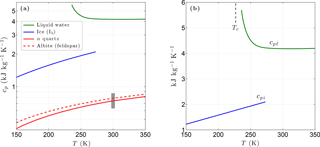
Figure 1(a) Variation of the specific heat with temperature for liquid water, ice, and two common minerals (quartz, albite). The vertical grey bar shows the specific heat range for most minerals at 300 K. Panel (b) shows the specific heat of liquid water and of ice in more detail. The vertical dashed line shows the temperature of the liquid–liquid critical point (Tc).
In permafrost, the enthalpy at temperature T consists of two components: one associated with the vibrational modes of the molecular lattice and the other due to the latent heat associated with the phase change of water:
Here, cp is the specific heat of the bulk material, ρℓ is the density of liquid water, and ΔHfus is the specific enthalpy of fusion for water. Differentiating Eq. (3), the volumetric heat capacity at constant pressure, defined by , is given by the sum of the lattice-vibration and latent-heat terms:
Since the density of air is much less than that of the other permafrost constituents, the lattice-vibration term is well approximated by the volume-weighted sum of the specific heats of the matrix materials, liquid water, and ice:
assuming ϕa<1.
Below 500 K, the specific heat of most matrix minerals is strongly temperature dependent, primarily due to the energies associated with the acoustic and optical modes of vibration (Kieffer, 1979, 1980). Due to the wide variety of crystalline mineral structures, simple analytic expressions for the temperature dependence of cpm encompassing all minerals are unavailable. However, the relatively smooth temperature dependence predicted by detailed models indicates the specific heat for a given mineral can be adequately represented by a three-term Taylor expansion over the temperature range of interest for permafrost (Fig. 1). For most minerals, the specific heat falls within the range 630–870 at 300 K and tends towards zero as T→0 K (Kieffer, 1979; Kittel, 1967; Robertson, 1988). Taylor expansions describing the temperature dependence ω(T) of cpm for most common mineral groups are incorporated into CVPM. The matrix specific heat is then given by , where is the specific heat of the dominant minerals at a standard temperature of 293.15 K.
Unlike most materials, experimental data for liquid water show an anomalous increase in specific heat (cpℓ) with decreasing temperature. Holten et al. (2012) explained this and other peculiar behaviors of supercooled water with a thermodynamic model that assumes the existence of a liquid–liquid critical point at low temperatures. Based on their interpretation of available thermodynamic data, the liquid–liquid critical temperature Tc is near 227 K. A least-squares fit to a composite of data reported by Angell et al. (1982) below 273 K and the International Association for the Properties of Water and Steam (IAPWS) 2008 values above 273 K provide the following relationships:
Values for the coefficients a1, a2, and bi are listed in Table 1.
Table 1Coefficients ai and bi in Eqs. (6)–(7) for the specific heat of liquid water and of ice (cpℓ and cpi in ).
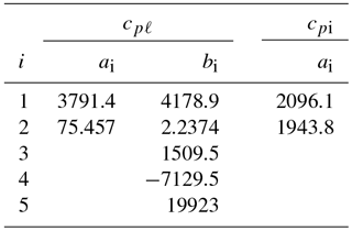
For water ice (Ih), lattice vibrations lead to a simple linear relationship between the specific heat cpi and temperature for T>150 K (Yen, 1981). Based on Yen's empirical relationship, cpi is well represented by
with a1=2096.1 and a2=1943.8 ().
2.2 Unfrozen water
Studies dating back to the mid-1800s show that a melt layer can stably exist at the interface between ice and a foreign substrate (e.g., a mineral grain), even at temperatures well below the bulk freezing temperature of water Tf (Dash, 2002; Dash et al., 1995). A melt layer can similarly exist at the grain boundaries within polycrystalline ice. For both interfacial and grain-boundary melting, the liquid phase exists because it reduces the system's total free energy. Electrostatic interactions in molecular substances such as ice tend to be dominated by non-retarded van der Waals forces. In this case, the thickness of the liquid layer adjacent to a planar substrate is , where is the temperature below the bulk freezing point (Dash et al., 2006; Wettlaufer and Worster, 1995). A ramification of this behavior is that the melting and freezing of ice in contact with mineral grains occur over a range of temperatures, rather than at a distinct temperature. Depending on the value for the interfacial melting parameter λ, substantial amounts of liquid water can exist at temperatures well below Tf. For a planar substrate, the interfacial melting parameter is given approximately by
where Δγ is the difference in the interfacial free energy with and without the melt layer, and σ is a constant on the order of a molecular diameter (Wettlaufer and Worster, 1995). Imperfections due to internal disorder (polycrystallinity, point defects, dislocations) within the ice and irregularities (pits, scratches, steps) in the substrate's surface can greatly increase the magnitude of Δγ and thereby the effective interfacial melting parameter λ. Due to the irregular nature of mineral surfaces and the likely disorder within interstitial ice, reliable expressions for parameter λ are currently lacking for most Earth materials. Thus, λ is best determined experimentally for frozen ground.
Surface curvature also affects the interfacial free energy and hence the thickness of liquid water films surrounding mineral grains. By considering the detailed effects of curvature along with interfacial and grain-boundary melting, Cahn et al. (1992) found that the volume fraction of liquid water in a porous medium consisting of spheres with radius r can be described by the sum of two temperature-dependent terms:
The first term is due to the combined effects of interfacial melting at the surface of the spherical particles and grain-boundary melting within polycrystalline pore ice. The second term is associated with high-curvature areas on the ice–liquid interface (e.g., near mineral grain-contact points and where ice-grain boundaries approach mineral surfaces). Coefficients a1 and a2 depend on how the particles are packed. For simple cubic packing, a1=1.893 and a2=3.367, while for cubic close packing, a1=2.450 and a2=8.572 (Cahn et al., 1992). Earth materials are likely to have intermediate values for the packing coefficients. In addition to its dependence on particle size and temperature, the second term depends on the interfacial free energy at the ice–water interface (γsℓ). The curvature coefficient at this interface, , numerically evaluates to 0.0259 µm K (Cahn et al., 1992). Given the temperature dependencies, the interfacial/grain-boundary term () dominates for strong undercooling (ΔT), while the second term (ΔT−2) dominates as temperatures approach the bulk freezing point (Tf). As the particle size r decreases, the transition between the two behaviors shifts to larger ΔT values (colder temperatures). While the first term is inversely proportional to r, the second term has an even stronger dependence on particle size (). Both terms result in greater amounts of unfrozen water in fine-grained materials (Fig. 2). Experimental data with graphitized carbon black and polystyrene powders confirm the form of Eq. (9) for monosized particles (Cahn et al., 1992).
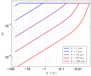
Figure 2Sensitivity of the volume fraction of liquid water ϕℓ to particle diameter d=2r using Eq. (9) with λ=0.36 µm K1∕3 and Tf=273.15 K, where . The porosity, ϕ=0.54 in this example, sets the upper limit on ϕℓ.
Although the particle and associated pore-size distributions in sandstones, limestones, and other rocks are often unimodal, those in mudrocks and soils typically are not (Kuila and Prasad, 2013). To accommodate a multimodal pore-size distribution, CVPM finds the total liquid water content by summing the contributions from the dominant modes. This is implemented in CVPM using a variant of Eq. (9):
where Ψj is the relative volume fraction of pores associated with the mode whose mean particle size is rj. Tests with sample pore-size distributions show the larger pore sizes contribute by far the most to the unfrozen water content. Thus, CVPM currently limits the number of modes contributing to ϕℓ to two (j≤2). In this case,
where (n2∕n1) is the ratio of the number density of pores with radius r2 to those with radius r1. As an example, suppose there are 100 times as many small pores (with a mean modal radius of 0.1 µm) as large pores (mean modal radius of 2 µm). Despite the greater number of small pores, the relative volume fraction of large pores is Ψ1=0.988, while that of the smaller pores is only Ψ2=0.012.
The undercooling ΔT used to evaluate the interfacial, grain-boundary, and curvature effects is measured relative to the bulk freezing temperature (Tf). For permafrost, pore pressures and dissolved solutes can significantly reduce Tf below the point at which pure water freezes (): 273.16 K at the triple point pressure Ptp=611.66 Pa (Guildner et al., 1976; Kittel, 1969; Nicholas and White, 2001). If θP and θs are the freezing-point depressions due to pressure and solutes, respectively, CVPM predicts the bulk freezing temperature using
When solutes remain dilute, the freezing-point depression due to impurities can be approximated using simple relationships such as Blagden's law (Delapaz, 2015). However, due to the insolubility of most solutes in ice, impurities become strongly enriched in the liquid pore water as permafrost freezes. As a result, solute–solute interactions become increasingly important, leading to significant deviations from the ideal behavior exhibited by dilute solutions. To account for the non-ideal behavior of aqueous electrolyte solutions at higher solute concentrations, CVPM uses the relationship
between the water activity aw and the solute freezing-point depression θs (Robinson and Stokes, 1959). Here, is the molar enthalpy of fusion at a standard temperature T∘, is the difference between the molar heat capacities of liquid water and ice, and R is the gas constant. Using established values for , , R, and T∘, Eq. (13) simplifies to
where θs is in Kelvin. The extent to which aqueous electrolyte solutions deviate from ideal behavior varies greatly, depending on the composition of the solute. As a result, the water activity aw depends on the particular solute and its mole fraction xs. Several expressions have been proposed for the water activity of non-ideal electrolyte solutions. CVPM uses the following equation proposed by Miyawaki et al. (1997):
where the coefficients α and β are solute dependent. For example, α=1.825, 4.754, and 11.859 for NaCl, KCl, and MgCl2, respectively, while , −49.37, and −404.5 (Miyawaki et al., 1997). Since essentially all the solutes are concentrated in the aqueous solution upon freezing, the solute mole fraction at any stage during freezing or thawing is given by , where is the solute concentration in the fully melted system (ϕi=0). Once xs and aw have been established, the freezing-point depression θs can be found by solving Eq. (14).
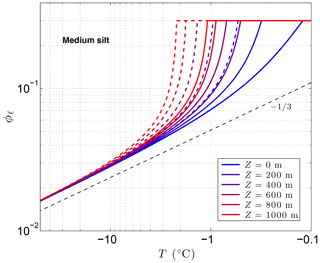
Figure 3 shows the sensitivity of the unfrozen water content ϕℓ to solutes predicted by CVPM for a medium-grained silt along with the temperature sensitivity needed to find the latent-heat component of the volumetric heat capacity C. The results show that even small amounts of solute can significantly affect ϕℓ and . As noted by Dash et al. (2006), the great sensitivity of ϕℓ to impurities is a likely cause for the considerable disagreement between the results of various unfrozen water experiments. An additional sensitivity can occur at cold temperatures if solute concentrations are sufficiently high. This occurs when the solution reaches its saturation limit, beyond which the solute begins to precipitate upon further cooling. This leads to the spike in values near −21 ∘C seen in Fig. 3b when aqueous NaCl concentrations exceed 0.005. The temperature at which the solute-saturation spike occurs varies, depending on the particular solute. Outside of the saturation limit, the largest values occur as the last bits of pore ice melt upon warming (ϕi→0). The volumetric heat capacity mirrors the temperature sensitivity but with minimum values established by the lattice-vibration term in Eq. (4).
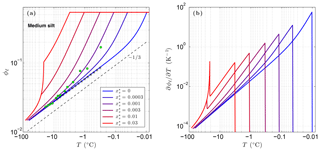
Figure 3Volume fraction of liquid water ϕℓ predicted for a medium-grained silt (r=15 µm) with NaCl solute concentrations ranging 0 to 0.03 (a). The depth z≈0 m, ϕ=0.54, and λ=0.36 µm K1∕3. Green dots show measured ϕℓ values for Fairbanks silt (ϕ=0.54) reported by Yuanlin and Carbee (1987). Stars correspond to the empirical equation fitting unfrozen water measurements in Fairbanks silt given by Anderson et al. (1973). Panel (b) shows the sensitivity of the liquid water content to temperature, .
As previously mentioned, the interfacial melting parameter is best determined experimentally for natural Earth materials. Inversion of unfrozen water data (shown in Fig. 3a) from Yuanlin and Carbee (1987) using CVPM yields a value of λ=0.36 µm K1∕3 for Fairbanks silt. Other parameters determined by the inversion are Ψ1≃1 and . Thus, the pore-size distribution for this material is approximately unimodal. In addition, trace amounts of impurities appear to have been present during the unfrozen water experiments despite efforts to eliminate them. The λ value determined for Fairbanks silt is about 100 times that determined for liquid films adjacent to smooth metal wires (Cahn et al., 1992), testifying to the importance of mineral surface irregularities and imperfections on the interfacial free energy in natural Earth materials. While more work needs to be done to quantify λ for the range of materials expected in permafrost, preliminary inversions for sedimentary materials (e.g., Suffield silty clay and kaolinite) yield values within ±10 % of that found for Fairbanks silt. At this point, the interfacial melting parameter λ does not appear to vary substantially amongst natural Earth materials.
Given that permafrost occurs at depths in excess of 1 km in some high-latitude areas and at 3–4 km beneath the polar ice sheets (Davis, 2001; MacGregor et al., 2016), the effect of pressure can be substantial on the bulk freezing temperature Tf and thereby the unfrozen water content ϕℓ. If the interstitial pores are freely connected to the planet's surface, the pore pressure is equal to the hydrostatic pressure (P=ρℓgz), where g is the acceleration of gravity and z is the depth below the surface. However, if the pore water is trapped, the pore pressure can be nearly equal to or exceed the lithostatic pressure (P=ρgz) (Turcotte and Schubert, 1982). In either case, the freezing-point depression due to pore pressure is
As water in permafrost is likely to be saturated with air, the appropriate value for coefficient a is K Pa−1 (Cuffey and Paterson, 2010). Since both pressure situations are known to occur in sedimentary basins, both are implemented in CVPM. The lithostatic effect is generally 2–3 times that of the hydrostatic effect. Not only does the pressure effect increase the unfrozen water content with depth, it also increases the temperature sensitivity () and therefore the volumetric heat capacity C (Fig. 4).
2.3 Thermal conductivity
Several mixing models are available for estimating the bulk thermal conductivity of multi-component systems. Of these, CVPM uses the Brailsford and Major (1964) two-phase random mixture (BM2) and three-phase (BM3) models, which are recommended as being the best for use with in situ Earth materials (Roy et al., 1981). Assuming a random mixture of pores and matrix material, the bulk thermal conductivity of permafrost can be described by the BM2 model:
where km is the conductivity of the matrix material, kp is the conductivity of the pores, and χ is their ratio (km∕kp).
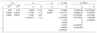
For matrix minerals, the thermal conductivity depends primarily on the temperature and mineral composition. Using thermal conductivity data obtained by Birch and Clark (1940a, b) over the temperature range 273–473 K, Sass et al. (1992) found the temperature dependence could be separated from the compositional dependence using a function of the form
where is the value of the matrix conductivity at a standard temperature of 273.15 K. As the ai coefficients are fairly insensitive to rock type, the effects of mineralogy and texture are almost entirely encapsulated in . A more recent analysis indicates the ai coefficients (Table 2) are slightly different for the mineral assemblages that dominate sedimentary rocks from those that occur in magmatic and metamorphic rocks (Vosteen and Schellschmidt, 2003). The upper temperature limit for Eq. (18) is set below the temperatures at which metamorphosis occurs in sedimentary rocks and well below the point where radiative heat transfer within crystal lattices becomes important (Clauser and Huenges, 1995). As very little thermal conductivity data exist for rocks and minerals below 273 K, the validity of Eq. (18) has yet to be tested at lower temperatures. The little data that do exist suggest that the transition from the intermediate-temperature behavior (Eq. 18) to the low-temperature behavior (km∝T3) (Parrott and Stuckes, 1975) generally occurs below 100 K. For example, in garnets, the transition occurs at 20–30 K (Slack and Oliver, 1971). We tentatively set the lower limit of validity for Eq. (18) at 150 K.
Table 2Coefficients ai and bi in Eqs. (18), (21)–(22), (24), and (26)–(27) for the thermal conductivity of matrix minerals, liquid water, ice, air, and CO2 gas (kx in ). For matrix minerals, and refer to the coefficients appropriate for magmatic/metamorphic and sedimentary mineral assemblages, respectively.
To find the thermal conductivity of the pores (kp), CVPM utilizes the three-phase BM3 model:
where the three phases (x) are liquid water, ice, and air. Here, , , and the ψx are the relative volume fractions of the pore's constituents (). Similar to other three-phase models, BM3 assumes phases 2 and 3 are randomly distributed within a continuous phase 1. If the relative volume fraction of any of the three constituents exceeds a threshold (ψx≥α), it is assumed that component is the continuous phase and kp is calculated directly from Eq. (19). A comparison of the results from the BM3 model in the limit ψ2→0 or ψ3→0 with those of the BM2 model suggests a reasonable choice for α is ∼0.75. If none of the relative volume fractions exceed α, Eq. (19) is used to calculate the conductivity of the pore space assuming each of the three components, in turn, is the continuous phase to produce values kcℓ (continuous liquid water phase), kci (continuous ice phase), and kca (continuous air phase). The pore conductivity is then found from a simple weighted average:
where the weights wx are based on the relative volume fractions ψx and the requirement that kp be continuous across the lines ψℓ=α, ψi=α, and ψa=α in three-phase space (Fig. 5).
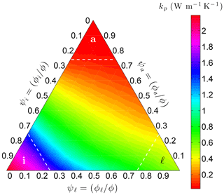
Figure 5Variation of the pore thermal conductivity kp on Earth at −10 ∘C with the relative volume fractions of liquid water (ψℓ), ice (ψi), and air (ψa) within the pores. Threshold α is 0.75 in this example.
For the thermal conductivity of liquid water kℓ, CVPM uses the simplified correlating equation recommended by Huber et al. (2012) for use at 0.1 MPa:
with coefficients ai and bi (Table 2). Although the formal lower limit for Eq. (21) is 273.15 K, Huber et al. (2012) find that it extrapolates in a physically reasonable manner down to ∼250 K (Fig. 6), producing results very close to those of the new detailed IAPWS formulation for kℓ. Thermal conductivity data for supercooled water do not appear to exist below 250 K at this time, preventing the development of accurate correlating equations at lower temperatures. This is a minor limitation for the thermal model as the relative amount of liquid water is expected to be small at colder temperatures.
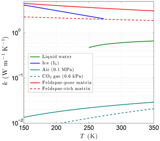
Figure 6Variation of the thermal conductivity with temperature for liquid water, ice, air (terrestrial atmosphere), CO2 gas (Martian atmosphere), and magmatic/metamorphic matrix minerals with (feldspar poor) and (feldspar rich).
Experimental data for the thermal conductivity of ice ki exist at temperatures as cold as 60 K. Based on these data, Yen (1981) recommends the function
for describing the temperature dependence of ki, with a1=9.828 and a2=0.0057 K−1.
For the terrestrial environment, the thermal conductivity of air ka can be separated into the sum of two terms: a “dilute gas” term ko that depends solely on temperature and a “residual” term Δk that depends on air density:
For the dilute gas term, Stephan and Laesecke (1985) recommend the correlating equation:
with ai coefficients (Table 2). At typical terrestrial surface pressures (∼0.1 MPa), the residual term Δk is (Stephan and Laesecke, 1985).
When considering permafrost on Mars, the thermal properties of a different atmospheric gas must be used. The Martian atmosphere is currently 95 % carbon dioxide, a gas that has a thermodynamic critical point at 304.107 K, 7.3721 MPa. At gas densities below 25 kg m−3, the effects of the critical region are small enough that the thermal conductivity can again be described by Eq. (23). In the case of CO2, the dilute gas contribution to ka is
where cint is the ideal gas heat capacity, kB is the Boltzmann constant, and 𝒞R is the reduced effective cross-section (Vesovic et al., 1990). The correlating equations for 𝒞R and cint provided by Vesovic et al. (1990) are
(coefficients ai and bi given in Table 2). At current Martian surface pressures (0.6 kPa), the residual component Δk is . Even when the Martian atmosphere was denser, the contribution of Δk to the overall thermal conductivity of the CO2 gas would have been quite small.
2.4 Compaction and heat-production functions
In sedimentary basins, overburden pressure causes the porosity ϕ to decrease with depth due to pressure solution and mechanical-compaction processes (Revil et al., 2002). The former process changes the mineral shapes in response to grain-contact stresses, while the latter results in the slippage and rotation of the grains. With increasing overburden pressure, the porosity ultimately reaches a residual (or critical) porosity ϕc that depends on the grain-shape and grain-size distribution. Shales and mudstones are much more easily compacted than sandstones due to the plate-like shape of the mineral grains. Although fairly sophisticated compaction models now exist, CVPM uses the simple frequently used compaction function attributed to Athy (1930),
to account for overburden pressures. This function has been successfully used in a large number of studies (Burns et al., 2005; Fjeldskaar et al., 2004). Here, ϕ0 is the porosity extrapolated to the surface, while hc is the compaction length scale. Parameters ϕ0 and hc depend on both the lithology and the effective stress history.
CVPM assumes the enthalpy-production rate S is associated with the decay of radionuclides. In this case,
where S0 is the radioactive heat-production rate extrapolated to the surface and hs is the heat-production length scale (Turcotte and Schubert, 1982). Surface heat-production rates S0 can vary from 0.002 to 5.5 µW m−3, depending on lithology (Rybach, 1988), while hs is typically on the order of 10 km.
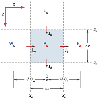
Figure 7Schematic showing the nomenclature associated with a control volume centered on grid point P for 2-D Cartesian (XZ) coordinates. The control volume is bounded by interfaces located at xw, xe, zu, and zd, through which enthalpy fluxes Jw, Je, Ju, and Jd pass. Grid points W, E, U, and D are located at the center of the neighboring control volumes (CVs). The nomenclature for 2-D cylindrical coordinates is completely analogous with R replacing X. Three-dimensional (3-D) Cartesian coordinates introduce an additional axis (Y) with neighboring grid points S and N.
The CVPM modeling system implements the governing equations in 1-D, 2-D, and 3-D Cartesian coordinates (X, XZ, XYZ), as well as in 1-D radial (R) and 2-D cylindrical (RZ) coordinates. Discretization follows the control-volume approach (Anderson et al., 1984; Minkowycz et al., 1988; Patankar, 1980) in which the problem domain is divided into a set of contiguous control volumes (CVs). Scalars such as temperature T and thermal conductivity k are computed at grid points located in the center of the CVs, while the enthalpy fluxes J are computed at control-volume interfaces (Fig. 7). Development of the CVPM permafrost model begins by integrating the two conservation equations (Eqs. 1–2) over a time step Δt. With velocity v≃0, the conservation equations become
where superscript n refers to the time step following standard numerical nomenclature (e.g., ). Equation (30) states the bulk density integrated over any control volume is time invariant. The conservation of enthalpy equation (Eq. 31) can be put in a more convenient form by noting
This follows from Eq. (3) and a Taylor series expansion. To provide the flexibility of running the model in either explicit, implicit, or fully implicit modes, the net heat flux into a control volume is approximated by a linear combination of values at either end of a time step:
The explicit/implicit weighting factor f can take any value between 0 and 1. Following Patankar (1980), the heat fluxes across the zu and zd interfaces in the vertical direction (see Fig. 7) are
where and are the “effective” conductivities at the upper and lower interfaces, defined by
with fractional distances
Subscripts used here indicate grid point and interface locations. For example, TP is the temperature at grid point P, while Ju is the heat flux across the interface located at depth zu. Fluxes across the other interfaces are defined in a completely analogous way. The use of effective conductivities guarantees that the heat fluxes exactly balance at an interface between materials with very different thermal properties (e.g., between a siltstone and an ice lens). The source-term integral in Eq. (31) is left in a very general form:
Substituting Eqs. (32)–(34) and (37) into Eq. (31), the discrete form of the enthalpy balance for a control volume centered on grid point P can be written as
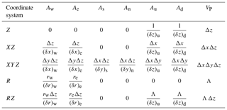
where the sums are taken over the values at the neighboring (nb) grid points (W, E, N, S, U, D). Putting all the geometric information into factors Ax and VP (Table 3), the discretization coefficients for the internal control volumes are
The primed counterparts of aW, aE, aS, aN, aU, and aD are identical, except that f is replaced by (1−f).
Table 3Geometric factors Ax and VP appearing in the enthalpy discretization (Eq. 39) for Cartesian and cylindrical coordinate systems. Dimensions of the control volume centered on grid point P are , , and , while the distances between grid points in the X direction are and . Distances between grid points in Y and Z directions are defined similarly. For radial geometries, .
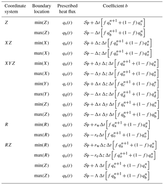
Consideration of the enthalpy balance shows that the discretization coefficients are slightly different for CVs adjacent to the boundaries of the problem domain. CVPM can be “forced” at the boundaries using either a prescribed temperature (Dirichlet) or heat-flux (Neumann) boundary condition (a convective boundary condition will be introduced in a later version). For a control volume adjacent to a boundary with a Dirichlet boundary condition, a factor of (4∕3) is introduced into the discretization coefficients (Eq. 39) associated with the boundary and the opposing interface. When the heat flux is prescribed on a boundary (Neumann BC), the coefficients associated with the boundary are zero and the specified heat flux appears in discretization coefficient b (Table 4). Boundary conditions along the edges of the problem domain are allowed to vary both spatially and temporally in CVPM.
Table 4Discretization coefficient b for a control volume adjacent to a prescribed heat-flux (Neumann) boundary condition.
To complete the setup of the discretization coefficients, the material properties must be specified at every grid point within the model domain. Parameters controlling these properties include material type, mean density of matrix particles ρm, mineral-grain thermal conductivity at 273.15 K, mineral-grain specific heat at 293.15 K, heat-production rate extrapolated to the surface S0, heat-production length scale hs, porosity extrapolated to the surface ϕ0, critical porosity ϕc, compaction length scale hc, degree of pore saturation Sr, dominant solute type, solute mole fraction in the fully melted system , interfacial melting parameter λ, mean diameter of larger mode pores d1, mean diameter of smaller mode pores d2, and the ratio of the number density of small pores to large pores (n2∕n1). The material “type” specifies which governing equations to utilize when finding the heat capacity and thermal conductivity (Sect. 2); types include pure ice and a variety of rocks, soils, organic-rich materials, fluids, and metals. Only a subset of these properties needs to be specified for non-porous layers (e.g., an ice lens or a borehole casing). Examples of the required thermophysical parameters are provided in Sect. 4 and in the CVPM version 1.1 modeling system user's guide (Clow, 2018).
Any temperature field can be used to set the initial temperature condition, including a user-supplied field (e.g., a measured temperature field), a CVPM-determined steady-state field consistent with the boundary conditions and material properties, or a field generated by a previous CVPM modeling experiment.
With the initial condition, boundary conditions, and discretization coefficients specified, the enthalpy-balance equation (Eq. 38) is solved recursively at each time step using the tridiagonal matrix algorithm (TDMA) for 1-D models and the line-by-line method with TDMA for 2-D and 3-D models. Given their temperature sensitivities, the thermophysical properties (ϕℓ, ϕi, C, k, etc.) are updated at every time step. In order for the numerical scheme to remain unconditionally stable, all of the discretization coefficients must be non-negative. This consideration leads to the numerical stability condition:
which must be satisfied in all the CVs at each time step for the scheme to remain unconditionally stable.
Model verification was conducted in two phases. In the first phase, the general model structure and numerical implementation were tested by comparing model results with analytic solutions for a series of simple heat-transfer problems without phase change. Test problems included steady-state and transient boundary conditions, homogeneous and composite media with fixed thermal properties, materials whose thermal properties vary linearly with temperature, and materials with and without radiogenic heating. In all cases, maximum model errors ϵ are on the order of 0.1 mK or less under the test conditions (spatial resolution, time step, etc.). For most cases, max(ϵ) ranges 1 µK to 0.01 pK. Since analytic solutions are unavailable for simultaneously testing all of the model physics, the second testing phase consisted of separately testing each physics module to guarantee it properly simulates the appropriate governing equations (Sect. 2).
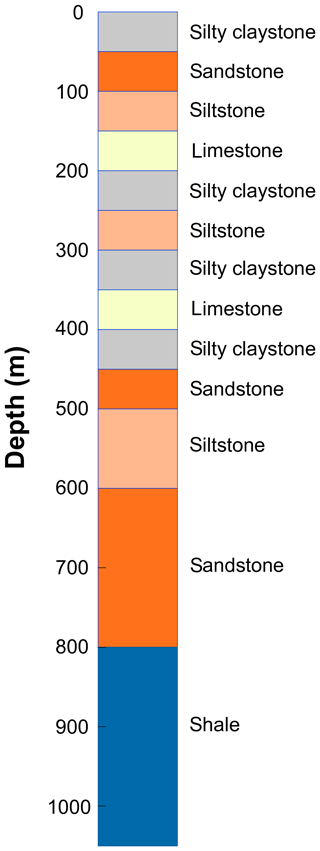
To illustrate the capabilities of the CVPM model, several examples are provided in this section based on the response of a thick vertical sequence of sedimentary rocks to changing boundary conditions. The sequence consists of flat-lying mudrock, carbonate, and sandstone units of various thicknesses (Fig. 8). Values of the parameters controlling the thermophysical properties (Sect. 2) are listed in Table 5. Heat-production rates are from Rybach (1988), while the compaction length scale is loosely derived from values found for a partially exhumed basin on the Arctic slope of Alaska (Burns et al., 2005). Pore spaces are assumed to be fully saturated with water throughout the geologic section []. Sodium chloride, present at relatively low levels when the sediments are completely thawed (), is the dominant pore-water solute.
Table 5Thermophysical parameters for the sedimentary rock units in Fig. 8. Parameters include thermal conductivity of matrix particles at 0 ∘C, (); density of matrix particles, ρm (kg m−3); specific heat of matrix particles at 20 ∘C, (); heat-production rate extrapolated to surface, S0 (µW m−3); heat-production length scale, hs (km); porosity extrapolated to surface, ϕ0; critical porosity, ϕc; compaction length scale, hc (km); degree of pore saturation, Sr; solute mole fraction in the fully melted system, ; interfacial melting parameter, λ (µm K1∕3); effective diameter of larger mode pores, d1 (µm); effective diameter of smaller mode pores, d2 (µm); ratio of the number density of small pores to large pores, n2∕n1.

4.1 Permafrost response to ice-age cycles
The first simulation explores the response of the sedimentary sequence to surface-temperature changes over the last ice-age cycle. The upper boundary condition is based on the surface-temperature history determined for the Greenland Ice Sheet during the Holocene and Wisconsin glacial period by Cuffey and Clow (1997) and the Eemian interglacial by the NEEM Community Members (2013). To construct the upper BC for the permafrost simulation, the Greenlandic temperature history was rescaled and shifted to yield an 8 K warming between the Last Glacial Maximum (LGM) and the early Holocene and a mean surface temperature of −11 ∘C during the 1800s (Fig. 9). For the most recent period, upper boundary temperatures warm 2.5 K between the mid-1800s and 1980 and an additional 2.5 K by the present time, similar to the record for the Arctic Coastal Plain of Alaska (Clow, 2017). The temperature history was replicated back several ice-age cycles to allow for model spin-up. At the lower boundary (depth 2 km), the conductive heat-flux qb was fixed at 60 mW m−2, slightly above the continental average. To initialize the model, the subsurface-temperature profile was assumed to be in a steady-state condition at 255 ka with the mean surface temperature over an ice-age cycle. For the spatial grid, 2 m thick control volumes were used above the 550 m depth. Below this, the grid spacing Δz increased progressively to 50 m near the lower boundary. To explore the response of permafrost well below the surface, a 20-year computational time step (Δt) was deemed sufficient.
With the above setup, CVPM was run forward in its 1-D vertical mode from 255 ka to the present. During the last ice-age cycle, the base of permafrost Pd (defined by the 0 ∘C isotherm) is found to vary by 90 m in this example from 435 to 525 m (Fig. 9). Of greater physical significance is the maximum depth where interstitial ice is present in permafrost. Due to the freezing-point depression caused by interfacial, curvature, pressure, and solute effects, the base of ice-bearing permafrost (B-IBPF) is located 20–27 m above the Pd throughout the simulation. During the most recent ice-age cycle, the B-IBPF and Pd both reached their greatest depths at ∼14 ka, a delay of 10 kyr from the Last Glacial Maximum. Since then, these interfaces have been steadily rising. With the conditions of this simulation, the B-IBPF is currently located at 431 m in a silty claystone, about 22 m below the shallowest depth projected to have occurred following the last interglacial, while the base of permafrost Pd is currently at 467 m in the underlying sandstone unit. Both interfaces are predicted to be rising about 1 cm yr−1 at present, a rate that may be detectable with a carefully designed experiment.
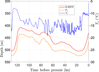
Figure 9Upper boundary condition (Ts) used to explore the response of a sedimentary sequence (Fig. 8, Table 5) to surface-temperature changes over the last ice-age cycle. Also shown are the depths for the base of permafrost (Pd) and the base of ice-bearing permafrost (B-IBPF) predicted by the CVPM model.
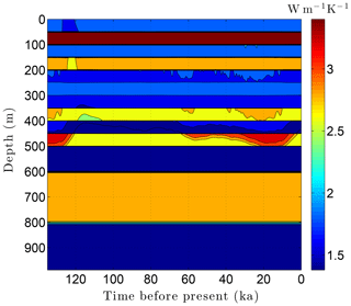
As the simulation confirms, the volume fraction of ice ϕi depends strongly on lithology (Fig. 10). This leads to zones with relatively high ice contents in coarse-grained sediments as is often observed in electrical resistivity geophysical logs (Hnatiuk and Randall, 1977; Osterkamp and Payne, 1981). An interesting facet of this behavior is that a pocket of ice-rich sandstone can occur below a fine-grained unit that has little or no ice (e.g., the silty claystone above the sandstone at 450 m in Fig. 10). Except near the B-IBPF, the ice content in coarse-grained materials appears to be relatively stable. In contrast, the volume fractions of ice ϕi and unfrozen water ϕℓ are much more dynamic in fine-grained materials over ice-age cycles due to their greater temperature sensitivity. In the upper two-thirds of the permafrost zone, up to 15 % of the water within silty claystones and limestones converts between ice and unfrozen water over ice-age cycles; the percentages are much higher in the lower third of the permafrost zone. Due to the phase change of water, a high heat capacity zone occurs just above the B-IBPF (Fig. 11). This zone, which tracks the B-IBPF over time, is roughly 100 m thick. Pockets of elevated heat capacity also occur in fine-grained materials closer to the surface, especially during periods affected by the warm interglacials. Thermal conductivity variations over an ice-age cycle are also primarily driven by the melting and refreezing of pore ice. Hence, conductivity variations are greatest near the B-IBPF, where conductivity changes of ±15 % occur (Fig. 12). In the upper two-thirds of the permafrost zone, thermal conductivity variations are greater in the fine-grained materials, at least on a percentage basis.
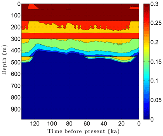
Figure 10Ice content ϕi variations over the last ice-age cycle within the example sedimentary sequence (Fig. 8). Unfrozen water ϕℓ variations (not shown) mirror the ice content fluctuations.
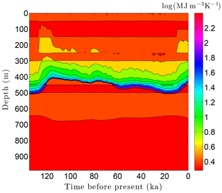
Figure 11Volumetric heat capacity C variations over the last ice-age cycle within the example sedimentary sequence (Fig. 8). The color mapping corresponds to log(C).
4.2 Permafrost response to drilling a deep borehole
We now return to the state of the sedimentary sequence simulated in Sect. 4.1 during the year 1980. By this time, temperatures in the upper 100 m of the sedimentary sequence have warmed in response to the 2.5 K surface warming since the termination of the Little Ice Age (∼1850). At greater depths, temperatures still reflect conditions earlier during the Holocene and the Wisconsin glacial period. With this initial condition, we consider the drilling of a 3 km deep borehole through the example sedimentary sequence (Fig. 8, Table 5) over a 60-day period. Drilling fluids pumped into the proposed 30 cm diameter hole at 30 ∘C interact thermally with the drill pipe and surrounding rock as they circulate to the bottom of the hole and back to the surface. As a result of the drilling processes, temperatures within the borehole warm within 700 m of the surface. The degree of warming depends on both depth and time as the drill bit advances into the warmer rocks below (Clow, 2015). Figure 13 shows the evolution of temperature changes (ΔTa) at the borehole wall during drilling based on the Szarka and Bobok (2012) wellbore model. This thermal drilling disturbance, when added to the initial 1980 temperature field, establishes the boundary condition at the borehole wall over the 60-day drilling period. To complete the CVPM setup for a cylindrical 2-D simulation of the permafrost surrounding the borehole, the problem domain was extended radially far enough (40 m) from the hole that the radial heat flux at the outer boundary could be set to zero. The heat flux on the lower boundary was again 60 mW m−2, while the upper boundary remained at its initial 1980 temperature (−8.5 ∘C). The vertical grid was identical to that used in Sect. 4.1, while the radial grid spacing increased progressively from 2.5 cm near the borehole to 2 m near the outer boundary. To resolve the rapid temperature changes that occur near the advancing drill bit, the computational time step was set to 0.2 days. The initial condition was provided by the values of all the state variables from the previous example (Sect. 4.1) during 1980.
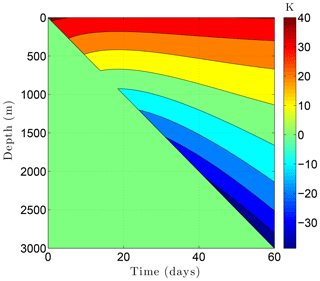
Figure 13Temperature change ΔTa at the borehole wall while drilling a 3 km borehole through the example sedimentary sequence (Fig. 8, Table 5) over a 60-day period. This thermal disturbance, when added to the initial temperature field, provides the boundary condition at the borehole wall during drilling. The drill bit advances from the surface on day 0 to 3 km on day 60.
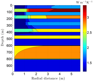
Running CVPM with the described initial and boundary conditions, the drilling disturbance is found to be great enough in this simulation to melt all of the permafrost ice within 1–2 m of the well by the time the borehole is completed on day 60 (Fig. 14). In this case, borehole electrical resistivity measurements used to detect ice in permafrost must be able to penetrate at least 1.5 m of rock to successfully detect ice. The exact location of the melting front is controlled partially by lithology, with it advancing further from the borehole in fine-grained high-conductivity sediments (e.g., limestones) than in coarser grained low-conductivity mudrocks such as siltstones. Sediment texture is a factor because it affects the volumetric ice content of a material in its undisturbed state. Although the thermal disturbance due to drilling is greatest inboard of the melting front, a substantial disturbance also occurs beyond the front, particularly in the upper couple hundred meters of permafrost, where the initial undisturbed temperatures were −7 to −9 ∘C (Fig. 15). Outboard of the melting front, the drilling disturbance extends further into the higher conductivity limestone and sandstone units than in the low-conductivity mudrocks. Because of the effect of temperature on the thermal conductivity of minerals, ice, and water, and because of the conversion of ice to liquid water, the bulk thermal conductivity drops about 30 % in the sedimentary units near the wellbore during drilling (Fig. 16). Attempts to infer the thermophysical properties of the sedimentary units from borehole temperature measurements using geophysical inverse methods must carefully consider these changes (Nicolsky et al., 2007).
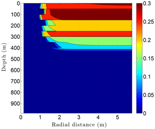
Figure 14Volumetric ice content ϕi in the sedimentary sequence (Fig. 8) penetrated by a newly completed 3 km deep borehole (day 60). Radial distance is measured from the central axis of the borehole.
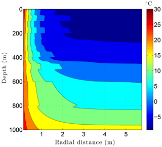
Figure 15Temperatures in the sedimentary sequence (Fig. 8) penetrated by a newly drilled 3 km deep borehole (day 60).
4.3 Permafrost response to the formation of a lake
Shallow lakes are ubiquitous on the Arctic Coastal Plain. In thermokarst areas, these lakes are constantly in transition, shrinking, enlarging, draining, and filling new depressions in response to changing temperatures and stream flows. The seasonal ice that forms on these lakes is categorized as “bedfast” ice if it freezes solid to the bottom of the lake, “floating” ice if some liquid remains beneath the ice throughout the winter, and “intermittent” if it is bedfast some years and floating during others. Whether a lake is a bedfast-ice lake or a floating-ice lake depends on whether the maximum seasonal ice-cover thickness () exceeds the depth of the lake. During the 1970s and 1980s, for lakes along the Beaufort Sea coast of Alaska was 2.0±0.2 m (Arp et al., 2012; Weeks et al., 1981). By 2010, the maximum seasonal ice thickness had decreased to about 1.5 m due to the warming climate in the region over the last few decades (Bieniek et al., 2014; Wang et al., 2017). Thus, 1.5 m deep lakes that would have been bedfast-ice lakes during the 1970s and 1980s would have transitioned to intermittent-ice lakes by 2010. Arp et al. (2012) recently provided lake–bed temperature data for seasonally ice-covered lakes near the Beaufort Sea coast. Based on these data, lakes whose depth is 0.5–1.0 m less than have a mean-annual temperature ∼4 K warmer than the surrounding tundra, while intermittent-ice lakes are about 9 K warmer.
Here, we briefly explore the permafrost response over a 35-year period to the instantaneous creation of a 200 m wide lake on the Arctic Coastal Plain of Alaska during 1980. The lake is assumed to be 1.5 m deep with a 100 m wide shallow (1.0 m deep) shelf and is assumed to occur in the same geologic terrain as in the previous two examples. Thus, the lake lies on a 50 m thick silty claystone unit which overlies deeper sedimentary rocks (Fig. 8, Table 5). To investigate the permafrost response, CVPM was used to simulate conditions along a 2-D vertical cross-section passing beneath the lake and surrounding tundra. Initial conditions were identical to those used in the previous example (Sect. 4.2). The upper boundary was set at the 1.5 m depth, i.e., at the bottom of the deeper portion of the lake. Temperatures on this boundary, which were used to force the model, varied depending on location. Beneath the tundra, temperatures were assumed to warm from the initial 1980 surface temperature (−8.5 ∘C) at 0.75 K decade−1, similar to recent trends observed along the Beaufort coast of Alaska (Clow, 2017; Wang et al., 2017). With these temperatures, the seasonal ice cover is projected to have been bedfast across the entire lake when it was first created and to have transitioned to intermittent over the deeper lake section towards the end of the simulation. Thus, lake–bed temperatures beneath the deeper portion of the lake, assumed to have initially been 4 K warmer than the surrounding tundra, were prescribed to have warmed until they were 9 K warmer than the tundra by 2015. Temperatures beneath the shelf were prescribed to be 4 K warmer than the tundra throughout the simulation. Temperatures beneath the tundra, shelf, and deeper portion of the lake provided the upper BC for the simulation. A heat-flux BC was prescribed on the lower boundary (qb=60 mW m−2), taken to occur at the 300 m depth in this example. The problem domain was extended laterally far enough beyond the lake that the heat flux across the outer boundaries could be set to zero. Vertical grid spacing was Δz=0.1 m in the upper silty claystone unit. Beneath this, Δz increased progressively to 10 m near the lower boundary. Horizontal grid spacing was 1 m beneath the lake and 5 m beneath the surrounding tundra. Although the prescribed upper BC does not include seasonal effects, the computational time step Δt was set to 0.1 years to satisfy the numerical stability condition (Eq. 40).
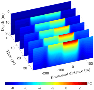
Figure 17Simulated permafrost temperatures over a 35-year period following the creation of a 200 m wide lake on a silty claystone unit. Depth is measured relative to the bottom of the deeper portion of the lake.
Running CVPM in its 2-D Cartesian mode for 35 years with the described boundary conditions, temperatures beneath the deeper portion of the lake are found to become warm enough to melt all of the pore ice at the lake–bed interface 19 years after the lake is created (Fig. 17). Thereafter, the melting front propagates downward in the upper silty claystone unit at ∼19 cm yr−1, creating a thaw bulb in its wake (Fig. 18). Lateral migration of the melting front is much more modest: ∼4 cm yr−1 where the deep section adjoins the tundra and ∼6 cm yr−1 where it meets the shallow shelf. By the end of the simulation, a thaw bulb has not yet begun to form beneath the shelf. There are two ramifications of the growing thaw bulb beneath the deeper section of the lake. (1) Fine-grained materials such as silty clay lose much of their mechanical strength once they thaw. In this state, the sides of the lake are much more vulnerable to erosion, which may lead to eventual drainage of the lake. (2) Old carbon stocks stored in the previously frozen permafrost are likely to decompose in the anaerobic thaw bulb and contribute greenhouse gases to the atmosphere (Anthony et al., 2016).
This paper presents the governing equations and numerical methods underlying the Control Volume Permafrost Model v1.1 which was designed to relax several of the limitations imposed by previous models. CVPM implements the nonlinear heat-transfer equations in 1-D, 2-D, and 3-D Cartesian coordinates, as well as in 1-D radial and 2-D cylindrical coordinates. To accommodate a diversity of geologic settings, a variety of materials can be specified within the modeling domain, including organic-rich materials, sedimentary rocks and soils, igneous and metamorphic rocks, ice bodies, borehole fluids, and other engineering materials. Porous materials are treated as a matrix of mineral and organic particles with pores spaces filled with liquid water, ice, and air. Functions describing the temperature dependence of the specific heat and thermal conductivity are built into CVPM for a wide variety of rocks and minerals, liquid water, ice, air, and other substances. For porous materials, the bulk thermal conductivity is found using a random two-phase (matrix particles, pores) relationship, while the conductivity of the pores themselves is found using a three-phase (liquid water, ice, air) mixing model. This scheme allows the bulk thermal conductivity to be determined for a wide range of porosities, water saturations ranging 0 %–100 %, and different planetary atmospheres. In addition to the lattice-vibration term (ρcp), the volumetric heat capacity C depends on a latent-heat term proportional to the change in liquid water content with temperature (). At temperatures below 0 ∘C, the unfrozen water content is found using relationships from condensed matter physics that utilize physical quantities (i.e., particle size) rather than non-physical empirical coefficients requiring calibration. Solute and pore pressure effects are included in the unfrozen water equations. Due to the insolubility of most solutes in ice, impurities become strongly enriched in the liquid pore water as permafrost freezes. To allow for the non-ideal behavior that occurs at high solute concentrations, the water activity aw is used to find the effect of solutes on the bulk freezing temperature of water Tf. With this approach, solute concentrations up to the eutectic point are allowed. Pore pressure effects on Tf are found in CVPM using either hydrostatic or lithostatic equations, whichever is more appropriate geologically. A radiogenic heat-production term is also included to allow simulations to extend into deep permafrost and underlying bedrock. For the current version of CVPM, liquid water velocities are assumed to be small enough that the associated advective heat flux is negligible compared to the diffusive heat flux.
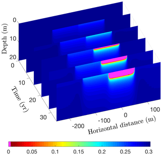
Figure 18Volume fraction of ice (ϕi) over a 35-year period following the creation of a 200 m wide lake. Magenta (ϕi=0) delineates the thaw bulb developing beneath the lake.
Numerical implementation of the governing equations is accomplished using the control-volume approach, allowing enthalpy fluxes to be exactly balanced at control-volume interfaces (e.g., at the interfaces between ice lenses, sedimentary units, bedrock, or a borehole casing). This approach was chosen because the expressions tend to be more accurate than with other methods near boundaries and where strong thermal or physical-property contrasts occur. Very large thermal-property contrasts generally occur near the water freezing point in permafrost. Despite the magnitude of the contrasts and the fact that the freezing front typically migrates over time, the numerical scheme used in CVPM remains stable as long as the stability criterium (Eq. 40) is satisfied. CVPM can be run in either explicit, implicit, or fully implicit modes.
CVPM has been designed for a wide range of scientific and engineering applications, and as an educational tool. The model is “forced” by changes in the boundary conditions at the edges of the problem domain. These conditions include user-prescribed temperatures and/or heat fluxes that are allowed to vary both spatially and temporally along the edges. The model is suitable for use at spatial scales ranging from centimeters to hundreds of kilometers and at timescales ranging from seconds to thousands of years. CVPM can be used over a broad range of depth, temperature, porosity, water saturation, and solute conditions on either the Earth or Mars. Through its modular design, CVPM can act as a stand-alone model or the physics package of a geophysical inverse scheme, or serve as a component within a larger Earth modeling system that may include vegetation, surface water, snowpack, atmospheric, or other models of varying complexity.
One of the goals of CVPM was to eliminate the empirical equations typically used to predict the unfrozen water content at temperatures below 0 ∘C, replacing them with condensed matter relationships containing quantities that both have a physical meaning and can be determined using relatively simple laboratory techniques or from geophysical logs. The physical quantities in the resulting equations tend to occur within reasonably narrow limits for the material categories defined in CVPM. Thus, if measurements of the physical quantities are unavailable, it may be possible to estimate the behavior of permafrost in a region from a geologic description of the area.
The CVPM source code, test cases, examples, and a user guide are publicly available at the Community Surface Dynamics Modeling System repository at https://csdms.colorado.edu/wiki/Model:CVPM (last access: 3 December 2018) and in Clow (2018). CVPM v1.1 is implemented in the MATLAB programming language and is distributed under the GNU General Public License v3.0.
The author declares that he has no conflict of interest.
This work was supported by the U.S. Geological Survey through a grant from
the Climate and Land Use Change Program. Any use of trade, firm, or product
names is for descriptive purposes only and does not imply endorsement by the
U.S. Government. The author thanks the referees for their careful reviews
and constructive suggestions which helped to improve the
manuscript.
Edited by: David Lawrence
Reviewed by: two anonymous referees
Arctic Climate Impact Assessment: ACIA Overview Report, Cambridge University Press, Cambridge, 1020 pp., 2005. a
Anderson, D. A., Tannehill, J. C., and Pletcher, R. H.: Computational Fluid Mechanics and Heat Transfer, Hemisphere Publishing Corp., New York, 599 pp., 1984. a, b
Anderson, D. M., Tice, A. R., and McKim, H. L.: The unfrozen water and the apparent specific heat capacity of frozen soils, in: Proceedings of the Second International Conference on Permafrost, Yakutsk, USSR, 13–28 July 1973, 289–295, 1973. a, b
Angell, C. A., Oguni, M., and Sichina, W. J.: Heat capacity of water at extremes of supercooling and superheating, J. Phys. Chem., 86, 998–1002, 1982. a
Anthony, K., Daanen, R., Anthony, P., Deimling, T. S., Ping, C.-L., Chanton, J., and Grosse, G.: Methane emissions proportional to permafrost carbon thawed in Arctic lakes since the 1950s, Nat. Geosci., 9, 679–682, https://doi.org/10.1038/NGEO2795, 2016. a
Arp, C. D., Jones, B. M., Lu, Z., and Whitman, M. S.: Shifting balance of thermokarst lake ice regimes across the Arctic Coastal Plain of northern Alaska, Geophys. Res. Lett., 39, L16503, https://doi.org/10.1029/2012GL052518, 2012. a, b
Athy, L. F.: Density, porosity, and compaction of sedimentary rocks, AAPG Bull., 14, 1–24, 1930. a
Bieniek, P. A., Walsh, J. E., Thoman, R. L., and Bhatt, U. S.: Using climate divisions to analyze variations and trends in Alaska temperature and precipitation, J. Climate, 27, 2800–2818, https://doi.org/10.1175/JCLI-D-13-00342.1, 2014. a
Birch, F. and Clark, H.: The thermal conductivity of rocks and its dependence upon temperature and composition, Part I, Am. J. Sci., 238, 529–558, 1940a. a
Birch, F. and Clark, H.: The thermal conductivity of rocks and its dependence upon temperature and composition, Part II, Am. J. Sci., 238, 613–635, 1940b. a
Brailsford, A. D. and Major, K. G.: The thermal conductivity of aggregates of several phases, including porous materials, Brit. J. Appl. Phys., 15, 313–319, 1964. a
Burns, W. M., Hayba, D. O., Rowan, E. L., and Houseknecht, D. W.: Estimating the amount of eroded section in a partially exhumed basin from geophysical well logs: an example from the North Slope, U.S. Geological Survey Professional Paper 1732-D, 2005. a, b
Cahn, J. W., Dash, J. G., and Fu, H.: Theory of ice premelting in monosized powders, J. Crystal Growth, 123, 101–108, 1992. a, b, c, d, e
Clauser, C. and Huenges, E.: Thermal conductivity of rocks and minerals, in: Rock Physics & Phase Relations, A Handbook of Physical Constants, edited by: Ahrens, T. J., American Geophysical Union, Washington DC, 105–126, 1995. a
Clow, G. D.: A Green's function approach for assessing the thermal disturbance caused by drilling deep boreholes through rock or ice, Geophys. J. Int., 203, 1877–1895, https://doi.org/10.1093/gji/ggv415, 2015. a
Clow, G. D.: The use of borehole temperature measurements to infer climatic changes in Arctic Alaska, PhD thesis, University of Utah, Salt Lake City, 250 pp., 2017. a, b
Clow, G.: csdms-contrib/CVPM: Version 1.1, Zenodo, https://doi.org/10.5281/zenodo.1237889, 30 April 2018. a, b
Cuffey, K. M., and Clow, G. D.: Temperature, accumulation, and ice sheet elevation in central Greenland through the last deglacial transition, J. Geophys. Res., 102, 26383–26396, 1997. a
Cuffey, K. M. and Paterson, W. S. B.: Physics of Glaciers, 4th Edn., Butterworth-Heinemann/Elsevier, Oxford, 693 pp., 2010. a
Dash, J. G.: Melting from one to two to three dimensions, Contemp. Phys., 43, 427–436, https://doi.org/10.1080/00107510210151763, 2002. a
Dash, J. G., Fu, H., and Wettlafer, J. S.: The premelting of ice and its environmental consequences, Rep. Prog. Phys., 58, 115–167, 1995. a
Dash, J. G., Rempel, A. W., and Wettlaufer, J. S.: The physics of premelted ice and its geophysical consequences, Rev. Mod. Phys., 78, 695–741, https://doi.org/10.1103/RevModPhys.78.695, 2006. a, b, c
Davis, N.: Permafrost: A Guide to Frozen Ground in Transition, University of Alaska Press, Fairbanks, Alaska, 351 pp., 2001. a, b
Delapaz, M. A.: Measuring melting capacity with calorimetry – Low temperature testing with mixtures of sodium chloride and magnesium chloride solutions, MS thesis, Norwegian University of Science and Technology, Trondheim, 60 pp., 2015. a
Fjeldskaar, W., Ter Voorde, M., Johansen, H., Christiansson, P., Faleide, J. I., and Cloetingh, S. A. P. L.: Numerical simulation of rifting in the northern Viking Graben: the mutual effect of modelling parameters, Tectonophysics, 382, 189–212, https://doi.org/10.1016/j.tecto.2004.01.002, 2004. a
Guildner, L. A., Johnson, D. P., and Jones, F. E.: Vapor pressure of water at its triple point, J. Res. Nat. Bur. Stand., 80A, 505–521, 1976. a
Hnatiuk, J., and Randall, A. G.: Determination of permafrost thickness in wells in northern Canada, Can. J. Earth Sci., 14, 375–383, 1977. a
Holten, V., Bertrand, C. E., Anisimov, M. A., and Sengers, J. V.: Thermodynamics of supercooled water, J. Chem. Phys., 136, 094507, https://doi.org/10.1063/1.3690497, 2012. a, b
Huber, M. L., Perkins, R. A., Friend, D. G., Sengers, J. V., Assael, M. J., Metaxa, I. N., Miyagawa, K., Hellmann, R., and Vogel, E.: New international formulation for the thermal conductivity of H2O, J. Phys. Chem. Ref. Data, 41, 033102, https://doi.org/10.1063/1.4738955, 2012. a, b, c
Kieffer, S. W.: Thermodynamics and lattice vibrations of minerals: 3. Lattice dynamics and an approximation for minerals with application to simple substances and framework silicates, Rev. Geophys. Space Ge., 17, 35–59, 1979. a, b
Kieffer, S. W.: Thermodynamics and lattice vibrations of minerals: 4. Application to chain and sheet silicates and orthosilicates, Rev. Geophys. Space Ge., 18, 862–886, 1980. a
Kittel, C.: Introduction to Solid State Physics, 3rd Edn., John Wiley & Sons, Inc., New York, 648 pp., 1967. a
Kittel, C.: Thermal Physics, John Wiley & Sons, Inc., New York, 418 pp., 1969. a
Kuila, U. and Prasad, M.: Specific surface area and pore-size distribution in clays and shales, Geophys. Prospect., 61, 341–362, https://doi.org/10.1111/1365-2478.12028, 2013. a
MacGregor, J. A., Fahnestock, M. A., Catania, G. A., Aschwanden, A., Clow, G. D., Colgan, W. T., Gogineni, S. P., Morlighem, M., Nowicki, S. M. J., Paden, J. D., Price, S. F., and Seroussi, H.: A synthesis of the basal thermal state of the Greenland Ice Sheet, J. Geophys. Res.-Earth, 121, 1–23, https://doi.org/10.1002/2015JF003803, 2016. a
Minkowycz, W. J., Sparrow, E. M., Schneider, G. E., and Pletcher, R. H.: Handbook of Numerical Heat Transfer, John Wiley & Sons, Inc., New York, 1024 pp., 1988. a, b
Miyawaki, O., Saito, A., Matsuo, T., and Nakamura, K.: Activity and activity coefficient of water in aqueous solutions and their relationships with solution structure parameters, Biosci. Biotech. Bioch., 61, 466–469, https://doi.org/10.1271/bbb.61.466, 1997. a, b
NEEM Community Members: Eemian interglacial reconstructed from a Greenland folded ice core, Nature, 493, 489–494, https://doi.org/10.1038/nature11789, 2013. a
Nicholas, J. V. and White, D. R.: Traceable Temperatures, 2nd Edn., John Wiley & Sons Ltd., Chichester, 421 pp., 2001. a
Nicolsky, D. J., Romanovsky, V. E., and Tipenko, G. S.: Using in-situ temperature measurements to estimate saturated soil thermal properties by solving a sequence of optimization problems, The Cryosphere, 1, 41–58, https://doi.org/10.5194/tc-1-41-2007, 2007. a
Osterkamp, T. E. and Payne, M. W.: Estimates of permafrost thickness from well logs in northern Alaska, Cold Reg. Sci. Technol., 4, 13–27, 1981. a
Parrott, J. E. and Stuckes, A. D.: Thermal Conductivity of Solids, Pion Limited, London, 157 pp., 1975. a
Patankar, S. V.: Numerical Heat Transfer and Fluid Flow, Hemisphere Publishing Corp., New York, 197 pp., 1980. a, b, c
Revil, A., Grauls, D., and Brévant, O.: Mechanical compaction of sand/clay mixtures, J. Geophys. Res., 107, 2293, https://doi.org/10.1029/2001JB000318, 2002. a
Riseborough, D., Shiklomanov, N., Etzelmüller, B., Gruber, S., and Marchenko, S.: Recent advances in permafrost modelling, Permafrost Periglac., 19, 137–156, https://doi.org/10.1002/ppp.615, 2008. a
Robertson, E. C.: Thermal properties of rocks, USGS Open-File Report 88-441, US Geological Survey, Reston, 1988. a
Robinson, R. A. and Stokes, R. H.: Electrolyte Solutions, 2nd rev Edn., Dover Publications, New York, 1959. a
Rothschild, L. J. and Mancinelli, R. L.: Life in extreme environments, Nature, 409, 1092–1101, https://doi.org/10.1038/35059215, 2001. a
Roy, R. F., Beck, A. E., and Touloukian, Y. S.: Thermophysical properties of rocks, in: Physical Properties of Rocks and Minerals, edited by: Touloukian, Y. S., Judd, W. R., and Roy, R. F., McGraw-Hill, New York, 409–502, 1981. a
Rybach, L.: Determination of heat production rate, in: Handbook of Terrestrial Heat-Flow Density Determination, edited by: Haenel, R., Rybach, L., and Stegena, L., Kluwer Academic Publishers, Dordrecht, 125–142, 1988. a, b
Sass, J. H., Lachenbruch, A. H., and Moses Jr., T. H.: Heat flow from a scientific research well at Cajon Pass, California, J. Geophys. Res., 97, 5017–5030, 1992. a
Slack, G. A. and Oliver, D. W.: Thermal conductivity of garnets and phonon scattering by rare-earth ions, Phys. Rev. B., 4, 592–609, 1971. a
Squyres, S. W., Clifford, S. M., Kuzmin, R. O., Zimbelman, J. R., and Costard, F. M.: Ice in the martian regolith, in: Mars, edited by: Kieffer, H. H., Jakowsky, B. M., Snyder, C. W., and Matthews, M. S., University of Arizona Press, Tucson, 1498 pp., 523–554, 1992. a
Stephan, K. and Laesecke, A.: The thermal conductivity of fluid air, J. Phys. Chem. Ref. Data, 14, 227–234, 1985. a, b
Szarka, Z. and Bobok, E.: Determination of the temperature distribution in the circulating drill fluid, Geosci. Eng., 1, 37–47, 2012. a
Turcotte, D. L. and Schubert, G.: Geodynamics, Applications of Continuum Physics to Geological Problems, John Wiley & Sons, New York, 450 pp., 1982. a, b
U.S. Arctic Research Commission Permafrost Task Force: Climate change, permafrost, and impacts on civil infrastructure, Special Report 01-03, U.S. Arctic Research Commission, Arlington, 2003. a
Vesovic, V., Wakeham, W. A., Olchowy, G. A., Sengers, J. V., Watson, J. T. R., and Millat, J.: The transport properties of carbon dioxide, J. Phys. Chem. Ref. Data, 19, 763–808, 1990. a, b
Vosteen, H.-D. and Schellschmidt, R.: Influence of temperature on thermal conductivity, thermal capacity and thermal diffusivity for different types of rock, Phys. Chem. Earth, 28, 499–509, https://doi.org/10.1016/S1474-7065(03)00069-X, 2003. a
Wang, K., Zhang, T., Zhang, X., Clow, G. D., Jafarov, E. E., Overeem, I., Romanovsky, V., Peng, X., and Cao, B.: Continuously amplified warming in the Alaskan Arctic: Implications for estimating global warming hiatus, Geophys. Res. Lett., 44, 9029–9038, https://doi.org/10.1002/2017GL074232, 2017. a, b
Watanabe, K. and Mizoguchi, M.: Amount of unfrozen water in frozen porous media saturated with solution, Cold Reg. Sci. Technol., 34, 103–110, 2002. a
Weeks, W. F., Gow, A. J., and Schertler, R. J.: Ground-truth observations of ice-covered North Slope lakes imaged by radar, CRREL Report 81-19, Cold Reg. Res. Eng. Lab., Hanover, 1981. a
Wettlaufer, J. S. and Worster, M. G.: Dynamics of premelted films: frost heave in a capillary, Phys. Rev. E, 51, 4679–4689, 1995. a, b
Yen, Y.-C.: Review of thermal properties of snow, ice and sea ice, CRREL Report 81-10, Cold Reg. Res. Eng. Lab., Hanover, 1981. a, b, c
Yuanlin, Z. and Carbee, D. L.: Tensile strength of frozen silt, CRREL Report 87-15, Cold Reg. Res. Eng. Lab., Hanover, 1987. a, b
Zhang, Y., Chen, W., and Cihlar, J.: A process-based model for quantifying the impact of climate change on permafrost thermal regimes, J. Geophys. Res., 108, 4695, https://doi.org/10.1029/2002JD003354, 2003. a


